What is Soil Resistivity?
Soil resistivity is a measure of how much the soil resists the flow of electricity. Soil Resistivity Testing is determining that measure. Therefore, is a critical factor in the design of systems that rely on passing current through the Earth’s surface. An understanding of the soil resistivity and how it varies with depth in the soil is necessary to design the electrical earthing systems. In an electrical substation, or for lightning conductors. Also for the design of earthing electrodes for substations and high-voltage direct current transmission systems needs this measurement. Because most substations, use the earth to conduct all or, a significant portion of fault current when there are earthing faults on the system.

Single wire return
In single-wire return power transmission system. The earth itself, used as the path of conduction from the end customers (consumers) back to the transmission facility. In general, there is some value above which the impedance of the earth connection must not rise. Also, some maximum step voltage must not exceed to avoid endangering people and livestock.
The soil resistivity value is subject to great variation, due to moisture, temperature and chemical content. Typical values are:
- Usual values: from 10 up to 1000 (Ω.m)
- Exceptional values: from 1 up to 10000 (Ω.m)
The Si unit of resistivity is the Ohm-meter (Ω.m);
You will find a wide range of typical soil resistivity values in the literature, Military Handbook 419 (MIL-HDBK-419A). Which contains reference tables and formulae for the resistance of various patterns of rods and wires buried in the soil of known resistivity. And because it’s copyright-free, these numbers widely copied, sometimes without acknowledgement.
Explaining Soil Resistivity Testing
Soil resistivity testing is the process of measuring a volume of soil to determine the conductivity of the soil. The resulting soil resistivity, typically expressed in ohm-meter.
This testing of the earth resistance is the single most critical factor in electrical earthing system design. This is true when discussing simple electrical design, to dedicated low-resistance earthing systems. Or to the far more complex issues involved in Earth Potential Rise Studies (EPR). Therefore, good soil models form the basis of all grounding designs. Furthermore, developed from accurate soil resistivity testing.
Getting ‘good’ soil models that accurately represent the geology. Much easier said than done! Because there can be numerous sources of error which can creep-in and catch the uninitiated or untrained out. Therefore, leading to an unsafe design.
Design a safe electrical earthing system
It is essential to determine the soil resistivity and maximum grid currents to design an electrical earthing system. The touch and step voltages are directly proportional to these values. Overly conservative values of soil resistivity and grid current will increase the cost dramatically.
Underestimating them may cause the design to be unsafe.
Soil Resistance (Investigations)
Soil resistivity investigations are necessary to determine the soil structure. There are a number of tables in the literature showing the ranges of resistivity based on soil types (clay, loam, sand, shale, etc).
These tables give only very rough estimates and therefore not relied on.
Resistance Changes
The soil resistivity can change dramatically with changes in moisture, temperature, and mineral content. To determine the soil resistivity of a particular site, earth resistance measurements take them using a soil resistivity tester with signal energy that matches the geology. Generally, the higher the signal, the higher the accuracy and errors from in-ground noise can be avoided.
Soil resistivity can vary both horizontally and vertically, making it necessary to take more than one set of measurements. Therefore taking more measurement data, the more informed the soil model.
Wenner 4-point soil resistivity test
The most widely used soil resistivity testing method developed, by F. Wenner in the early 1900s and called either the Wenner or four-pin method. Using four pins or electrodes driven into the earth along a straight line at equal distances of.
a, to a depth of b, the current passed through the outer pins while a voltage reading taken with the two inside pins.
Based on the resistance R, as determined by the voltage and current, the apparent resistivity calculated using the following equation, assuming ρ is small compared with a: ρa = 2πaR where it is assumed the apparent resistivity ρ, at depth a is given by the equation.
Interpretation of field measurements
Interpretation of the apparent soil resistivity based on field measurements is difficult. Up until recently, Uniform and two-layer soil models were the most commonly used soil resistivity models. However, recent innovations in Earthing Modelling software tools such as CDEGS (a form of finite element analysis.) And updates in standards, make multiple-layer soil models a practical reality today.
There should be no excuse to use the legacy uniform soils of yesterday. The objective of the soil model is to provide a good representation of the actual soil structure. Which is never uniform. And will usually exceed 3 layers in the majority of geologies. Therefore, leaving 2-layer models as an oversimplification.
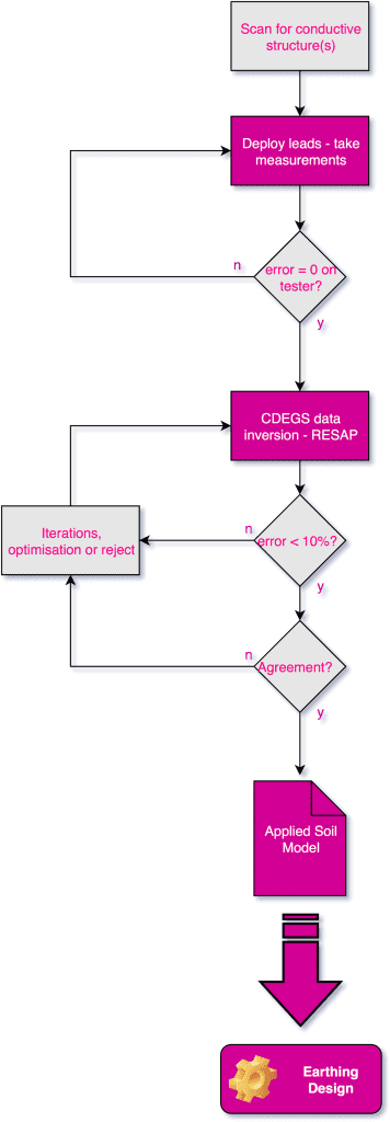
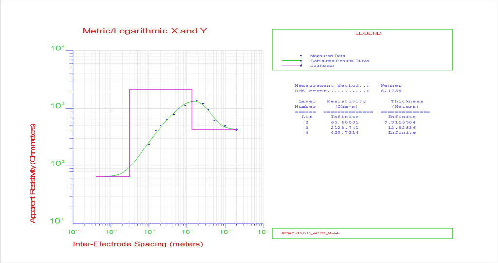
Soil Resistivity Testing Analysis
Interpretation of the data, done either manually for simple/small scale systems or by the use of computer analysis, such as CDEGS. There are commercially available computer programs that take the multi-layer soil structure data and mathematically calculate the soil resistivity and provide a confidence level for the tests to evaluate the error. Typical RMS error should not exceed 10% for the model considered valid, but this in itself is not the final factor.
Sunde developed a graphical method to interpret the test results.
The IEEE Std. 80 and IEC equivalent EN50522 standards
The IEEE Std. 80 and IEC equivalent EN50522 still require a degree of technical judgement is required to interpret the soil resistivity measurements to determine the value of the soil resistivity ρ, to use in the equations. IEEE Std. 80 presents equations to calculate the apparent soil resistivity based on field measurements as well as examples of Sunde’s graphical method.
Although the graphical method and equations are estimates only. They provide a useful basic uniform soil resistivity either to quickly compare other models. As part of the sense-making process. Or for use on a simple, small scale earth grid design. For everything else, the more representative multi-layer models need to be computed/calculated. This is normally done with the finite element analysis type software tool, CDEGS.
Conducting a Wenner 4-point soil resistivity test
When conducting a Wenner 4-point soil resistivity test, we need to consider the effects that the “Sphere-of-Influence” will have on our test, in two (2) ways:
- The distance our test is being conducted from any buried metallic objects, rail tracks, fence lines, etc. This distance should be equal or greater than the maximum (“a”) spacing of our test. In other words, if you are conducting a Wenner 4-point test with a maximum probe spacing of 60 meters (a 180-meter traverse), there should be no interfering ‘conductive’ objects (fence, buried metal pipes, etc.) within 60 meters of any part of the test.
- The probes used to conduct the test will have their own sphere-of-influence that they will generate based on the depth they are driven into the earth. For hand calculations, the probe depth may not exceed 1/20 of the spacing of the Wenner test. Advanced computer algorithms such as those used in finite element analysis software tool CDEGS, e.g. RESAP module can adjust for these differences, but the 1/20th rule is a good one.
If this article raised a couple of questions you want answering or you want to discuss a specific project – I am available. Also, a Free Trial of our Earthing Courses is available here.
Engage with us…
- Earthing Design Services & Lightning Protection Design – If high voltage power systems and lightning are causing you concern why not see how we can help with a quick ‘live chat’ below as a start.
- XGSLab – A complete software tool for the simulation of Power, Earthing, Grounding and Lightning Systems, get in touch to request a free demo.
- Get Certified – Start your journey to become certified in Power Systems Earthing & Design.