Introduction to the Wenner 4 Probe Test
The Wenner probe test is a geotechnical investigation method used to determine the electrical resistivity of the soil.
Soil resistivity testing can be carried out using different methods. The Wenner 4 Probe test is one of the most common of these. Furthermore, its one of the three most popular soil resistivity methods employed, to perform a soil resistivity test. Therefore, this piece describes how to carry out the Wenner 4 Probe Test Method
To complete a Wenner probe test, you will need the following equipment:
- Four electrodes (usually copper rods or pipes)
- A resistivity meter or multi-meter
- A hammer or other tool for driving the electrodes into the ground
Process for conducting a Wenner probe test:
- Determine the desired length of the probe. This will depend on the depth of soil you want to test and the spacing between the electrodes.
- Set up the electrodes. The electrodes should be spaced a set distance apart, typically 20 cm, 50 cm, or 100 cm. The center two electrodes are the current electrodes, and the outer two electrodes are the potential electrodes.
- Drive the electrodes into the ground, the electrodes should be driven to the desired depth.
- Connect the resistivity meter or multi-meter to the electrodes. The meter should be connected to the current electrodes and the potential electrodes.
- Take a reading. The resistivity meter will measure the resistance between the current electrodes and the potential electrodes.
- Repeat the process at multiple locations to get a representative sample of the soil.
- Calculate the average resistivity of the soil using the readings from each location.
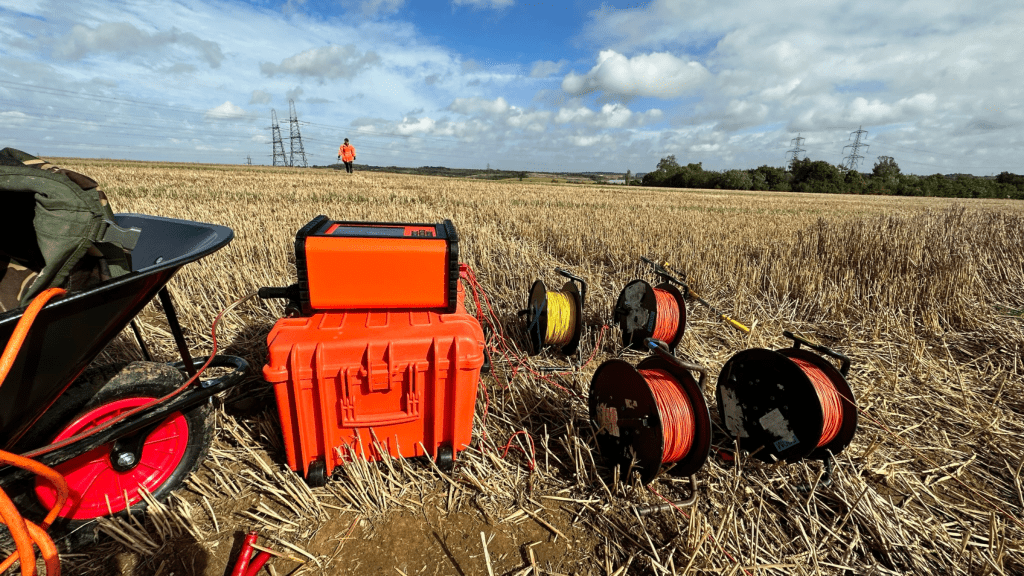
Wenner 4 Probe Soil Resistivity Testing Method
Wenner array is probably the most labour-intensive of all the ways when performing the longer traverses. Hence, this method can call on up to four people to accomplish the task in a sensible time frame.
On the other hand, it is the optimal Soil Resistivity Testing Method (to date) of choice for Earthing Designs, due to its ratio of received voltage per unit of transmitted current.
Therefore, this means the Wenner Method is considered one of the more ‘reliable’ methods for testing soils to deeper depths.
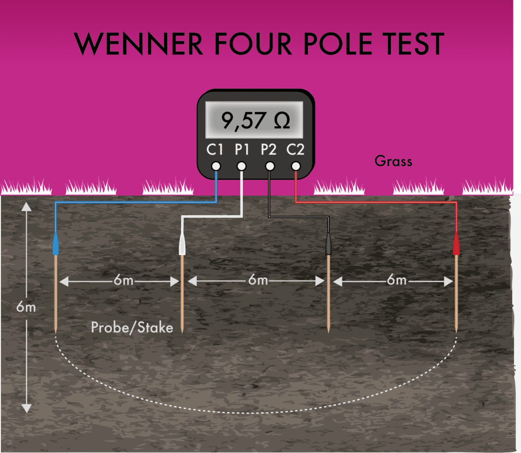
Soil Resistivity Testing Methods – The Wenner 4 Probe test.
In the Figure above, the illustration shows how the probe spacings relate to the apparent depth under test, e.g. a 6m probe spacing. As a result, indicates the soil resistivity at a depth of ~6m.
So, do your soil testing using the Wenner 4-probe method specified in IEEE Standard 81 Part 1, BS EN 50522 or BS 7430.
So, for each measurement traverse. The pin spacings (between adjacent probes) need to begin at 6″ to 12”. And increase after that by a factor of approximately 1.5. Then, up to the maximum pin spacing chosen for that traverse.
Therefore it is highly desirable to have 2 to 3 traverses centred at different locations. Likewise, whose maximum probe spacing (between adjacent probes) reaches a distance that exceeds the maximum extent of the substation. For example, its largest diagonal dimension (and any other facility associated with the substation), preferably twice this diagonal dimension or more. While avoiding the influence of buried metallic structures.
Hence, requiring a number of additional shorter traverses (0.15 up to 6m) to obtain data sufficiently representing soil conditions at shallower depths throughout the site.
So, the Wenner 4 Probe Soil Resistivity Test method consists of four-electrode probes; two are for the current injection. And two for potential measurement
Wenner 4 Probe Test Arrangement
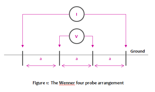
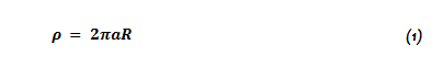
Figure 1 (above) shows the Wenner 4 Probe Test Arrangement. Soil resistivity calculation formula Equation 1: shows the soil resistivity formula associated with the Wenner 4 Probe test method.
Where R is the resistance measured by the machine
a is the spacing of the probe
So, an example of a probe to probe spacings for a Wenner 4 probe configuration is as follows:
When designing to IEC BS EN 50522, there are 14 predefined spacings PER traverse.
Probe Spacing
3.0
4.5
6.0
9.0
13.5
18
27
36
54
81
100
How Deep Does The Wenner 4 Probe Method Test
Readers often ask, “How deep does the Wenner 4 Probe method test?” The way the Wenner method works is by emitting an electrical signal into the ground via the probes and measuring the returning signal. The probes only penetrate the ground by a few inches, but the electrical signal itself can penetrate many meters.
So, just to reiterate… the probes only physically penetrate a few inches. However, the volume of geology under test is determined by the spacing between each test probe. So, in theory, the testable depth is only limited by the instrument’s strength of the signal and the deployable distance between probes.
BS EN 50522 describes a typical set of probe distances that work on the most size of earth electrodes.
By the way, why not drop us a line or chat for more info on the peculiarities of BS EN50522 verses IEEE Std 81.
Given the capital importance of the soil resistivity data for adequate Earthing, Grounding system design calculations require a well-defined quality control program in the field to demonstrate that readings are valid.
So, when capturing the data from a Wenner Soil Resistivity Test, this data then needs to be processed further:
Soil Resistivity Testing Data Inversion
The measured soil resistivity data needs to be inverted to obtain equivalent multi-layer soils to before using in the subsequent Earthing/Grounding Design.
So, this interpretation requires to account for electrode pin depth. Also, any irregular pin spacings (due to obstacles in the field). And known buried metallic structures. That mildly to moderately distort the measured values.
Therefore, chose one or more suitable soil models for the Earthing Study. From those obtained from all measurement traverses. Also, explain these choices in the final report.
So, currently, the accepted practice for the Data analysis method is to use specialist software tools. Such as CDEGS RESAP or XGS_SRA (From XGSLab) to deliver a 1-D (one dimensional) optimised model. But note, 2-D pseudo sections are not readily usable for Earthing Design. However, the pseudo segments are growing in popularity for geological exploration/investigations. Also, can provide useful insights (3-D finite volume data) for Earthing System Design.
Therefore, it’s wise to have any approximations to the soil model justified for good measure. Account for soil structure model variations due to local, and seasonal variations by developing soil model structure limiting cases.
As a result, it can’t be understated. Just how important reliable, ACCURATE Soil Resistivity data is for the subsequent Earthing Design. Also, it is the absolute foundational requirement that all following safety calculations for touch and step voltages are derived.
Alternative Soil Resistivity Testing Methods:
Engage with us…
- Earthing Design Services & Lightning Protection Design – If high voltage power systems and lightning are causing you concern why not see how we can help with a quick ‘live chat’ below as a start.
- XGSLab - A complete software tool for the simulation of Power, Earthing, Grounding and Lightning Systems, get in touch to request a free demo.
- Get Certified – Start your journey to become certified in Power Systems Earthing & Design.
If you are Interested in having a Soil Resistivity Test on
We offer a variety of services, including our Field Services, with one of them being our Soil Resistivity Test, allowing us to measure the capacity of the ground to pass an electrical current, which will be used throughout many projects.