Awareness of step and touch potential, caused by a rise of earth potential. Is essential for anyone working on high-voltage power transmission and distribution systems above 1 kV.
A rise of earth potential
A rise of earth potential is caused by electrical faults that occur at electrical substations. Power plants, or high-voltage transmission lines. Therefore, short-circuit current flows through the plant structure. And equipment and into the earthing electrode. Since the Soil Resistivity is not zero. Therefore, any current injected into the earth at the earth electrode produces a ‘Rise of Earth Potential’. This earth potential rise (EPR) is concerning an infinitely distant reference point. The resulting rise of earth potential can cause hazardous voltage. And, many hundreds of metres away from the actual fault location. Thus, many factors determine the level of hazard. Including available fault current. And, soil type, soil moisture, temperature, underlying rock layers. Also, clearing time to interrupt the fault.
The rise of earth potential is a safety issue in the coordination of power and telecommunications services. A RoEP event at a site such as an electrical distribution substation. May expose personnel, users or structures to hazardous voltages. These hazards referred to as Step and Touch Potential risks.
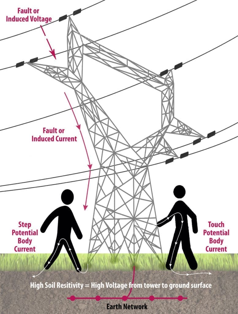
Step Potential Body Current
Step Potential is the voltage between the feet of a person standing near an energised earthed object. It is equal to the difference in voltage, given by the voltage distribution curve. Between two points at different distances from the “electrode”. A person could be at risk of injury during a fault simply by standing near the connected object.
Touch Potential Body Current
Touch potential defined as the difference between the maximum Rise of Earth Potential. And the minimum surface potential within a 1 m radius of the earthed plant. There are cases where the touch potential could be nearly the full voltage across the earthed object. Therefore, if that object is earthed. At a point remote from the place where the person is in contact with it. For example, a crane earthed to the system neutral. And that contacted an energised line would expose any person in connection with the crane. Or its uninsulated load line to a touch potential nearly equal to the full fault.
Charles Dalziel
The person who pioneered much of the early work into how the human body responds to electrocution. Was Charles Dalziel, pictured below. He conducted experiments studying his body responses to electrocution presumably, there were not many volunteers for the task! Fortunately, he did survive (86 yrs young). And the results from his experiments formed the basis of IEC 60479-1, Effects of Current on Human Beings and Livestock.
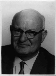
What Dalziel was able to determine is that response to stress voltages is probabilistic. Which means that once a given threshold accepted as tolerable. Not everyone in a given general population is going to survive! This is because every individual is different, has differing tolerance to the stress voltage before the heart fibrillates. For example, an elderly person with a heart condition. Or a very young child is likely to be more ‘at risk’ than say a fit/healthy adult.
To this day there remains some controversy between EU regions and authorities. Regarding where the touch and step threshold voltages should sit. However, with recent amendments to the IEC standards. The remaining area of ambiguity largely centre’s on the selection of appropriate fault clearance times.
Step and Touch Potential hazards
Based on the recent amendments to BS EN 50522 and IEEE Std.81. Step and Touch voltage safety has become the driving criterion for safe Electrical Earthing Design. It used to be the 1-ohm earth mat that would ensure safety, but this is no longer the case. Current wisdom and best practices adopted by both the IEEE and IEC bodies. Agree that the real hazard posed by a Rise of Earth Potential. Is whether the human heart (or given animal) can withstand (survive) the current flow. Resulting from a difference in potential when touching a piece of equipment. Or standing nearby, e.g. the step potential and touch potential or voltage.
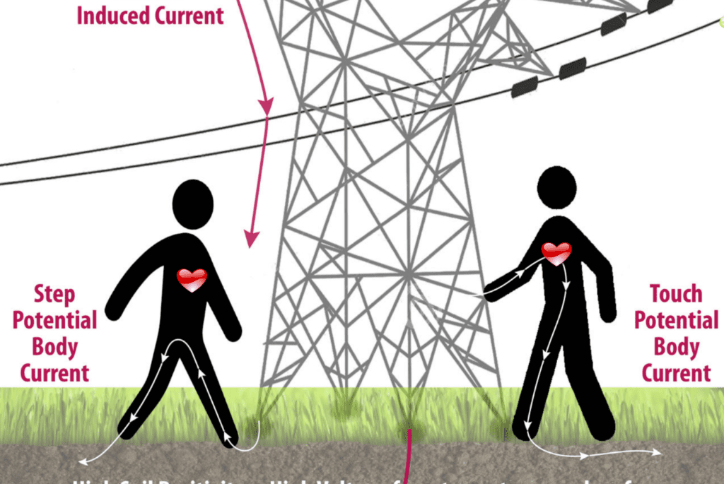
You can see in the image above, that the heart is further away from the body currents in the Step Potential case, whereas, in the Touch Potential scenario the electrons flow almost directly through/around the heart itself. Ignoring shoe resistance, this is a key reason why the permissible voltage thresholds for Step Potentials can be far higher than those for Touch Potential.
Reducing the Risks – Step and Touch Potential
Once a Rise of Earth Potential Study has identified the risks – There are a number of basic essential measures available to the specialist Earthing Consultant to reduce step and touch risks (mitigation). The complexity comes in knowing how to apply, combine and configure these into a robust earthing solution that controls and maintains the surface voltages in such as way as to not exceed the permissible thresholds of the heart AND within the practical financial constraints of a budget. Some of the hardware to incorporate into a design includes:
- Grading conductors
- Conductor meshes
- Vertical electrodes
- Horizontal electrodes
- Deep bore electrodes
- Counterpoise electrodes
- Earthed planes
- Rod groups
- Proper Bonding arrangements
- Ground conditioning agents*
- High resistance surface layers, such as crushed rock, stone, rubber, tarmac, etc.*
* For most cases, high resistivity surface layers should be considered more as a secondary mitigation method, e.g. the earthing strategy should be to achieve a safe base design (where practicable) without surface layer mitigation or soil conditioning agents.
Other non-hardware related mitigation may include a Risk Management Approach where the risks are ‘managed’ through the application of processes and procedures to avoid injury.
Electrical Earthing Online Training
Learn more about a Rise of Earth Potential and safe earthing design. In our Online Introduction to Earthing Course Free Trial Available.
Engage with us…
- Earthing Design Services & Lightning Protection Design – If high voltage power systems and lightning are causing you concern why not see how we can help with a quick ‘live chat’ below as a start.
- XGSLab – A complete software tool for the simulation of Power, Earthing, Grounding and Lightning Systems, get in touch to request a free demo.
- Get Certified – Start your journey to become certified in Power Systems Earthing & Design.