Finite element analysis (FEA) is a numerical method for solving problems in engineering and applied sciences. It is used to analyze and predict the behavior of complex systems. Such as structures, machines, and electronic devices, under a wide range of conditions (i.e. forces, energies, vibration, heat, fluid flow, and other physical effects).
Finite element analysis shows how something will perform when stressed. Whether it will break, wear out, or work the way it was designed BEFORE it is created, installed or built in the ‘real’ world.
It is called analysis, but in the product development process. It is used to predict what is going to happen when the product is used.
What is Electromagnetic Inference?
Let’s start at the begining…Electromagnetic inference (EMI) is the interference or disruption of the normal functioning of electronic or electrical systems caused by the emission of electromagnetic energy. It can be caused by a variety of sources, such as lightning, electric motors, and radio transmitters. EMI can affect the performance of electronic devices and systems, potentially causing them to malfunction or even fail. To prevent or mitigate the effects of EMI, electronic devices and systems may be designed with special shielding or filtering to reduce their susceptibility to interference.
How does FEA work?
In FEA, a complex system is divided into a number of smaller, simpler elements that can be analyzed individually. The behavior of each element is then determined using mathematical equations. The results are combined to predict the overall behavior of the system. This allows engineers to analyze and understand the performance of a system in great detail. Along with identify potential problems or weaknesses.
FEA is widely used in a variety of industries, including aerospace, automotive, civil engineering, and electrical engineering. It is a powerful tool that can help to design, optimize, and test complex systems. Reducing the need for costly and time-consuming physical testing.
Finite element analysis helps predict the behaviour of products affected by many physical effects, including:
- Mechanical stress
- Electro magnetics
- Mechanical vibration
- Fatigue
- Motion
- Heat transfer
- Fluid flow
- Electrostatics
- Chemical iterations
Greymatters Global Perspective
Finite Element Analysis from our perspective. So as an Electrical Earthing Design Consultancy Firm is in the Power System, Electrical Earthing, and Electromagnetic Fields.
Why is Finite Element Analysis important in Electrical Earthing Design?
Finite element analysis (FEA) is a numerical method for solving problems in engineering and applied sciences. Such as electrical earthing design. It is a powerful tool that can be used to analyze and predict the behavior of complex systems. Such as the performance of an electrical earthing system under various conditions.
Unlike oil, water or other visible sources from failed structures, electrical earth leakages are invisible. But can be fatally dangerous.
As Electrical Earthing Design Consultants we need to know the behaviour of any earth leakage i.e. the uncontrolled release of electrical energy, from failed or damaged structures.
We need tools that allow us to model the potential energy field. Converting the invisible (electrical energy) into real world forces. FEA does this through finite element mathematical analysis.
For the mathematical calculation we use the computer-modelling software called CDEGS. Which is an acronym of (Current Distribution, Electromagnetic Fields, Grounding and Soil Structure Analysis), which has many engineering modules in its suite, each dedicated to a specific task.
Reasons why FEA is important in electrical earthing design:
- FEA allows engineers to analyze and optimize the design of an earthing system before it is built, reducing the need for costly and time-consuming physical testing.
- FEA can help to identify potential problems or weaknesses in the design of an earthing system, allowing engineers to make necessary changes before the system is constructed.
- FEA can simulate the performance of an earthing system under a wide range of conditions, including different soil types and moisture levels, temperatures, and loadings. This can help to ensure that the earthing system is robust and reliable.
- FEA can be used to optimize the design of an earthing system, reducing the amount of materials and labor required, and potentially lowering the overall cost of the system.
Finite Element Analysis & CDEGS
CDEGS software, an Integrated Software Package used for testing for Power System, Electrical Earthing/Grounding, Electromagnetic Fields and Electromagnetic Interference.
CDEGS software is a powerful set of integrated engineering software tools designed to accurately analyse problems involving electrical earthing, electromagnetic fields, electromagnetic interference including AC/DC interference mitigation studies and various aspects of cathodic protection and anode bed analysis with a global perspective. Starting literally from the ground up.
Available versions
Crucially, not all CDEGS versions are the same or perform in the same way – there’s more detail in previous blog
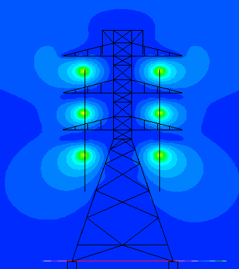
Firstly, CDEGS HIFREQ version only (top-end module) computes conductor currents and electromagnetic fields generated by an arbitrary network of energized conductors anywhere above or below ground for normal, fault, lightning and transient conditions.
CDEGS models simple and multi-component conductors, including bare, coated pipes and pipe-enclosed cable systems buried in complex soil structures.
Lastly, CDEGS and its sub packages, coupled with toll-free support from the world’s leading R&D design team in these specialties, provide you with an array of cost-effective solutions for problems ranging from simple grounding grid designs to the behaviour of complex networks of aboveground and buried conductors energised by lightning or other transients. Therefore by providing you with AutoCAD and other software supporting DXF integration, CDEGS can work seamlessly with your own Structural design files.
Whether you are confronted with a complex Earthing design, EMF studies, electromagnetic compatibility and interference problems or a lightning/surge study, you can rely on GreyMatters accredited use of accurate CDEGS, powerful and integrated software components for a realistic, optimized solution.
Obviously extensive scientific validation of the software using field tests and comparisons with analytical or published research results, have been conducted for over thirty years. The validation, conducted by CDEGS developers “SES” as well as other independent researchers, is documented in hundreds of technical papers published in the most reputed international journals.
The CDEGS software package
SES started the development of the CDEGS software package in 1972, with the creation of the MALT engineering module (a basic circuit theory based app). Since that time, CDEGS has undergone steady growth and refinement. It is composed of eight engineering modules RESAP, MALT, MALZ, TRALIN, SPLITS, HIFREQ, FCDIST, and FFTSES.
CDEG Capabilities
Briefly stated, CDEGS capabilities are:
- Soil resistivity analysis and soil structure interpretation.
- Earthing analysis: arbitrary soil structures any frequency & transients.
- Line constants for overhead and buried conductors or complex pipe-enclosed cable arrangements.
- Load, fault & transient current distribution (in neutrals, shields, etc.).
- Cathodic protection analysis of complex buried networks.
- Inductive, conductive and capacitive interference in shared corridors.
- Frequency and time domain analysis of electromagnetic fields generated by arbitrarily energized conductor networks (substations, transmission & distribution lines, industrial plants, etc.).
Top 1% – Knowing that proof of competence is a key pre-requisite for the project supply chain, GreyMatters is in the top 1% of Earthing consultancies in Europe to formally be FULLY CDEGS accredited/certified, hence there are no nasty surprises as you’re in safe hands! With over 20+years of sector experience – there isn’t a scenario we haven’t already come across and solved.
Engage with us…
- Earthing Design Services & Lightning Protection Design – If high voltage power systems and lightning are causing you concern why not see how we can help with a quick ‘live chat’ below as a start.
- XGSLab – A complete software tool for the simulation of Power, Earthing, Grounding and Lightning Systems, get in touch to request a free demo.
- Get Certified – Start your journey to become certified in Power Systems Earthing & Design.