What are the procedures for creating an HV Earthing System Design? Also, how might these differ from an LV Earth design?
Firstly, although the principles underpinning HV and LV earthing are similar, the approaches are very different.
Probabilistic Approach
The first huge difference is the recognition that HV electrical earthing design is probabilistic in nature. Whereas LV earthing is far less so.
What do I mean?
Engineers have used a more deterministic approach to allowable step and touch voltages for many years. Based on previous versions of standards such as IEEE-80 / BS 7354 / BS 7430.
The weakness with a ‘deterministic’ approach is that a standardised safety criterion applies across all sites, regardless of the physical setting and variables. In other words, the deterministic approach tries to get a one-size-fits-all to work, which we know, for the most part, doesn’t work.
More recently, IEC EN 50522 and IEC EN 62305 introduced a ‘probabilistic’ approach to earthing design. The standards use well-understood risk management procedures to assess individual site risks (likelihood and consequence).
This probabilistic approach considers the fibrillation risk (from the step or touch voltage). And also, the associated risk from the fault frequency and circulation of people on or near the area under study.
You can learn more about the probabilistic approach here.
So, clearing up some of the main differences between HV and LV earthing design. Then, let’s concentrate on the procedures and process. So, if this is your first project involving an HV earthing system. This article gives you a good starting point.
HV Earthing System Design Procedure
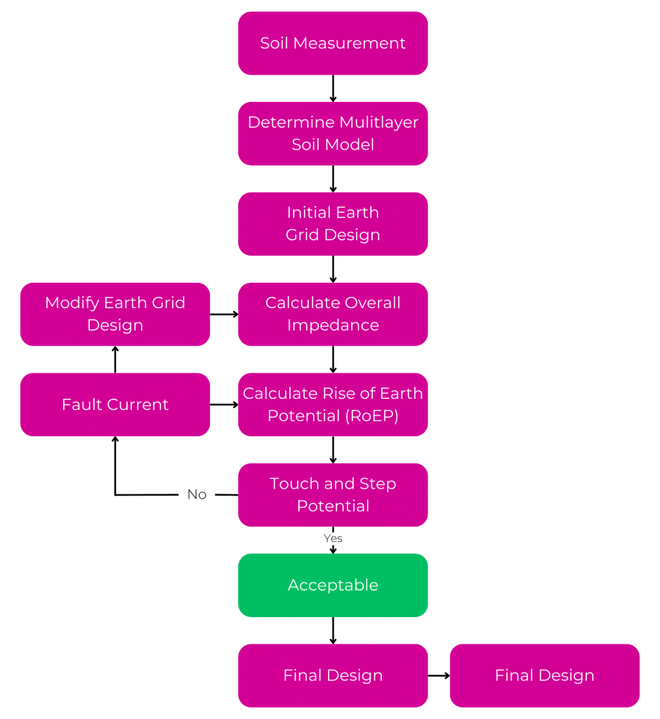
Soil resistivity
Understanding the geology is a fundamental requirement of earthing design. Knowing how the ground behaves during electricity discharge is vital. Without this knowledge, all subsequent calculations will be for nothing, zero, nada!
So, when soil resistivity testing, it is critical to use a tester capable of eliminating errors. You can learn more about how to avoid the most common mistakes when measuring soil resistivity here.
Once you are confident in the soil resistivity measurements, a soil ‘model’ can be carefully derived. The next step relies on experience and sound engineering judgement to flesh out the first initial iteration of the electrode design.
Effective Earthing Design Procedure
Applying calculations to the initial design to examine its safety performance. So this means doing these calculations manually or using a spreadsheet. However, this approach is not advisable. To make hand calculations accessible to the average engineer, many manual calculations rely on simplifying the problem. Therefore, this leads to massive inaccuracies. Moreover, when lives are at stake, introducing another source of error must be avoided!
So, the preferred modern approach is to model the ‘real-life’ scenario using the latest FEA software tools. These tools do the heavy lifting and compute the outcome using tools such as CDEGS software.
These tools give you the ability to represent what is happening across the site. Thus, visually, by plotting the surface voltages. Therefore, if the magnitude of the voltage is too much. You can see straight away where the hot zone is. And start to do something about it on the next iteration of the electrode design.
This iterative approach to design means any areas where the surface voltages are found to be excessive show up clearly. Armed with this insight, the effort can be directed toward these problem areas to make them safe. Optimising in this way can save a lot of money on expensive-to-install copper. Hence, where the conductors and electrodes are arranged only where they are needed. Also, without compromising safety.
So, once the touch voltage, step voltage and impedance meet the criteria. Then, the final design iteration can be submitted for approval. And also, employed for other disciplines, such as the lightning protection system design.
Verification and Validation (V&V).
Finally, once installed, the electrode arrangements are physically measured, inspected and certified for energisation. Carrying out earth tests to confirm, verify and validate (V&V). That the electrical performance figures match those predicted by the calculated/modelled design. Also, closing the circle. And, confirming the electrode arrangements perform as an effective earthing solution.
So, if you are new to Earthing System Design Procedures in a project or scheme. Then, I hope this is a useful introduction to the process.