During the past 27 years as an Electrical Earthing Design Consultant, delivering independent Earthing advice and consultancy across the world, no matter what the country, there are common mistakes that people make. Knowing that “Pre-warned is Pre-armed”, in this piece I list some of the most common practices good and bad, so that you can benefit from the shared learning. I should point out this is observational, and intended as a guide only – local regulations and standards should be implemented where necessary.
1. BAD Practice:
To use or rely on generic soil resistivity data. Also to assume a 2-layer soil model is sufficient.

1. BEST Practice:
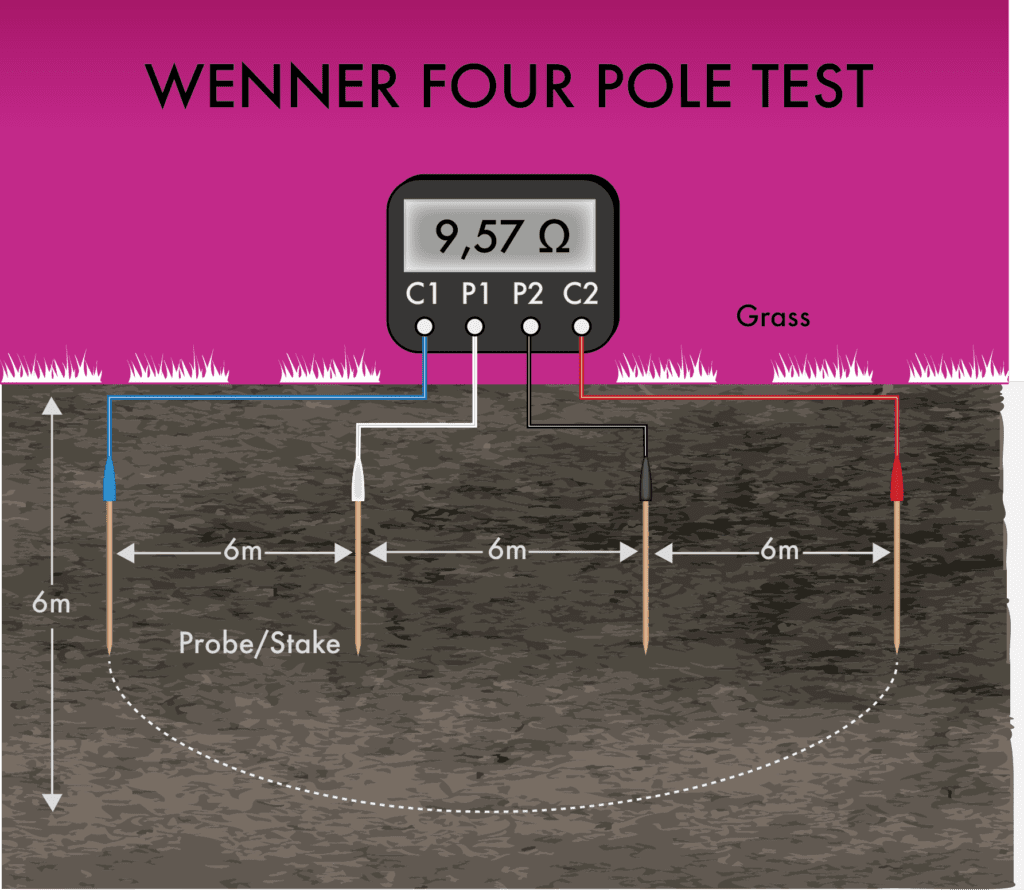
Take plentiful Wenner 4-pole measurements across a wide range & adequate probe spacings. Ensure probe spacing’s start at 150 mm with an interval that increases no greater than 50% from spacing to spacing, and a maximum ‘a’-spacing (see BS7430 or IEC 50522) that is greater than the earthing system’s sphere-of-influence. This could equate to 100’s meters between probes for a large system.
2. BAD Practice:
To use cheap meters to collect Wenner 4-pole soil resistivity data.
2.BEST Practice:
Use direct-current (DC) induced polarisation meters (IP) that can account for error during tests by stacking multiple soundings and ensure that the instrument has sufficient signal voltage to match the geology. The best instruments are capable of delivering 400-800 V, which means in-ground noise can be dominated for the optimum confidence in the accuracy, whatever the geology.
3. BAD Practice:
To use apparent resistivity for your soil model.
3. BEST Practice:
Use Earthing software to run a least-square minimisation algorithm, such as, the Steepest-Descent, Levenberg-Marquardt, Fletcher-Powel, G-Conjugate, Conjugate Gradients, or Simplex methodology in order to produce a robust 1-D soil model.
4. BAD Practice:
To design isolated Earthing systems.
4. BEST Practice:
To bond all your Earthing systems together ‘globally’ to avoid hazardous EPD (earth potential differences) event from occurring.
5. BAD Practice:
To rely on ground enhancement backfills.
5. BEST Practice:
Always pursue establishing a low enough impedance without relying on chemical additives or ground doping, e.g. by the native soil. Consider any ground enhancement as a last resort with the exception of bentonite clay with a moisture delivery system to prevent the clay from drying out or approved conductive material.
6. BAD Practice:
To rely on water pipe, building steel, steel rebar in the building foundation, gas pipes, and/or fire sprinkler risers, as the sole primary Earth electrode.
6. BEST Practice:
Use a dedicated copper Earthing electrode system that is engineered and rated to cope with a primary electrical fault, objectionable currents, harmonics, and human safety issues found at your site. Any conductive structures to be bonded as a secondary equalisation and/or surface voltage grading function to mitigate touch and step potentials.
7. BAD Practice:
Forget to bond conductive elements and structures.
7. BEST Practice:
Bond water pipes, building steelwork, steel rebar in the building foundation, conductive gas pipes, fire sprinkler risers, to the Earthing system at the first service disconnect to ensure they are at the same potential. Additional bonding may be required as part of a more detailed bonding strategy.
8. BAD Practice:
To use Earthing software that only uses two (2) soil layers.
8. BEST Practice:
To use software capable of calculating Earthing systems in at least six (6) soil layers. Conveniently or not, mother-nature rarely produces a geology with less than 3 layers so over-simplifying to 2 layers is a very real risk.
9. BAD Practice:
To use software that relies on Circuit Theory or only provides a blanket (equipotential) step and touch voltage across the entire area.
9. BEST Practice:
Use software capable of calculating individual step and touch voltages at one-meter distances from any given object and that can accurately account for the capacitive, inductive (electromagnetic) and resistive couplings that are found on larger Earthing systems.
10. BAD Practice:
To attempt hand-calculations when dealing with human safety in high-voltage environments (1,000 volts or greater) or pretend that you have the experience needed to deal with the complexity of Earthing and Electrical Power Earthing Systems.
10. BEST Practice:
Contact an engineering firm specialising in Earthing and grounding.
If any of the above bad practices resonates with you or you would like advice on a particular challenge then please drop us a line on the chat tool below, or contact through the normal channels.
Find out what questions to ask before you hire your next electrical earthing consultant here.
[wptab name=’About’]
 Ian Griffiths
Ian is a Principal Consultant at GreyMatters, with 26 years experience solving HV earthing, EMC, and lightning problems for clients worldwide. When he’s not busy studying problems and designing solutions, you can find him mountain biking, sailing and racing motorbikes in the summer. In the winter he tends to head off to the mountains chasing the snow with friends and family. Ian holds a Master’s Degree, and Degrees in both Mechanical and Electrical disciplines, and is one of the top 1% accredited CDEGS consultants and advisor to international utility companies, data-centre and infrastructure developers globally.
[/wptab]
[wptab name=’Latest Posts’]
Recent Posts by Ian
CDEGS – Avoid being caught-out with The Wrong Trousers
How to avoid explosive risks from surges due to lightning and transient faults
Soil Resistivity and soil resistivity testing methods – a few short videos
GreyMatters – Protecting 100,000 lives through Earthing Design
[/wptab]
[end_wptabset]