We receive a lot of questions asking how to do a Wenner test or what are the steps in a soil resistivity testing. The key thing to take away is that once you have the appropriate equipment. The act of ‘doing’ a Wenner Soil Resistivity Test is not that complicated. However, you must take a consistent, systematic approach to the task, otherwise, the chances of error creeping-in are high and will appear discretely, sometimes without you noticing (unless you have the means to process the data on-site during the task).
It’s imperative to understand, errors in the data at this early stage of the process for electrical earthing design can be disastrous. Disastrous for safety from the system, and disastrous from a functional perspective for the earthing system (grounding).
Here is a collection of Soil Resistivity Survey Video(s). Some are from us, the team at Greymatters. And, others sourced from Youtube. Can you spot the real guys?
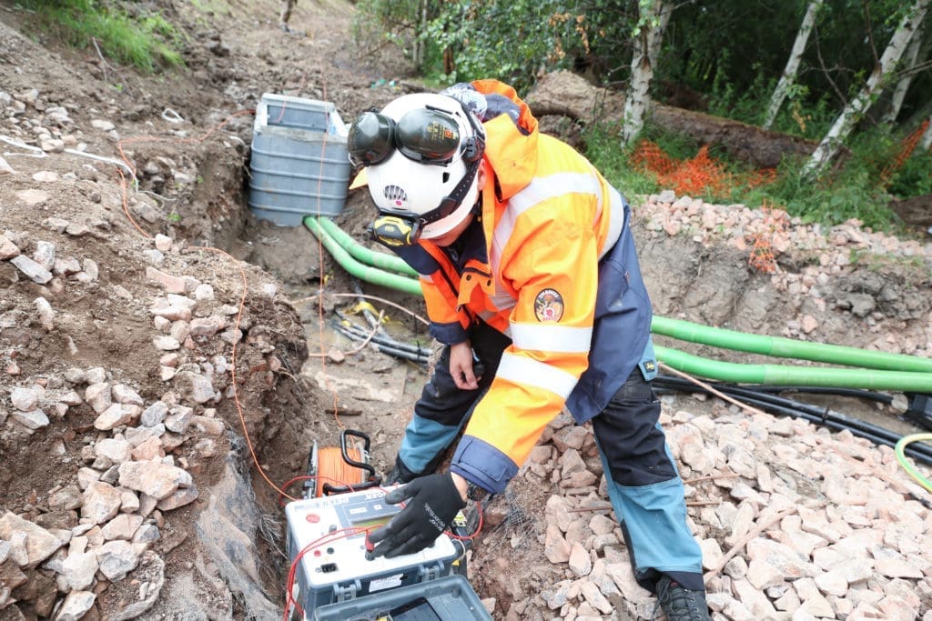
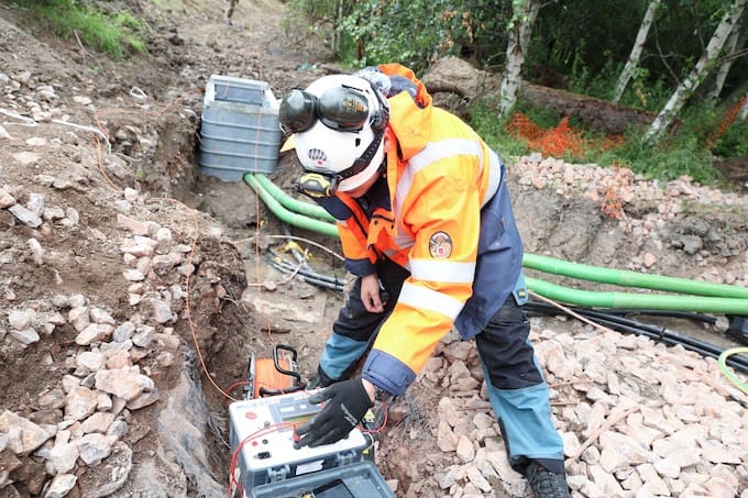
Here’s Ian of Greymatters (not feeling 100%) carrying out a field soil resistance survey.
What is Soil Resistivity
Soil resistivity is a measure of how much the soil resists the flow of electricity. Therefore, it is a critical factor in the design of systems that rely on passing current through the Earth’s surface. So, an understanding of the soil resistivity and how it varies with depth in the soil is necessary to design the grounding system in an electrical substation, or for lightning conductors. Also, needed for the design of grounding (earthing) electrodes for High-voltage direct current transmission systems. So, in single-wire earth return power transmission systems. The earth itself used as the path of conduction. Hence, from the end customers (the power consumers). And, back to the transmission facility.
Therefore, in general, there is some value above which the impedance of the earth connection must not rise. Also, some maximum step voltage not to exceed to avoid endangering people and livestock.
The soil resistivity value is subject to great variation, due to moisture, temperature and chemical content.
Soil Resitivity Testing – 3 Helpful Tips to Avoid Common Mistakes
So, in this video, we take a real-life scenario in the mountains (Wind Turbine farm) and point out a few tips and ‘tricks of the trade’ to reduce error when carrying out Wenner soil resistivity testing in geologically challenging terrain.
Sufficient signal strength from the instruments must penetrate for the ground structure under-study. Therefore enabling adequate sounding-depth. Also, analysis for the subsequent Soil Model produced for a safe HV Earthing Design.
In-Video Intro [00:00]
We’ve got our tester kit, consisting of two DET 2’s, a set of leads (pairs, e.g. 4 leads in total), the leads span 300 metres total, so we’re getting probe spacings up to 100 metres.
We’ve got multiple copper rods, in this case, because we’re sitting on granite [cough]. We want to be able to get as maximised contact with the surface layer as possible so that we can get [cough] good return signal.
Often, you won’t get a chance to take soundings directly on construction sites. Because it’s too busy. And, too much plant. Together with, too many risks. And the ground itself probably made up. So it’s of little real value because it’s all kind of imported.
[1:00] So hunt out … [in this case we’ve gone a little bit Ray Mears, if you’re not familiar with Ray Mears – he’s a survival expert] but anyway we’ve gone a little bit Ray Mears outside of the construction site, to find a place that has been undisturbed – and here we are in the forest.
[1:16] We’ve just laid out the pins – first pin and point leads, the first pin is about, [I dunno] 10 inches apart spaced – this sets the trend for analysis later on.
[1:29] It’s really important you get a close spacing, first of all. Also, to see where the tipping point is for the layers.
[1:36] So, the next phase is really getting the spacings out. To about 54 – 100 metre intervals. So, we’re on about a 300 metre run (of leads) into the forest.
TIP 1: Multiple Probes [01:58]
Right, we’re using multiple probes to increase the surface contact. Also, with the signal on the sounding. So, we get a good return and more reliable resistivity test results, basically.
[2:15] This is what they look like, the potential probe on one side, then we’ve got three probes on the other. The mole grips are there because it’s practicably all we had available. But just to give you an idea.
[2:26] We’re using copper probes, driven to about 3 inches – 4 inches deep, with multiple stack connectors on, which then go into the leads [I can show you … these particular leads have seen a bit of action, but anyway], it just gives you an idea of what we’re doing, and cos the [multiple] on the current signals especially, multiple probes they allow better connection, so you’ve effectively got a much bigger probe area in contact … it sends s decent signal through, for the instrument to pick up … that’s the theory.
[3:21] [try and get you in focus … there you go … all good] … 51.8 – mark that off against the probe spacing. And then what happens then is that is the rule reading. – So, it then gets processed. Software processed. – Therefore, to actually give the correct, apparent reading. And this we repeat numerous soundings. Up to 300-metre spacings sometimes. So, it can be quite a time-consuming activity.
Tip 2: Surface Test [4:03]
A really useful tip for the modelling side of soil resistivity is to get the immediate surface layer tests and sounded – which means probe spacings typically 4 – 6 inches apart [don’t know if you can see that] but this is just to set the trend when it comes to the analysis side of things.
[4:34] So a useful tip. – Get that in, it may not form part of the formal report. But it does set the scene for the model analysis.
Tip 3: Angle [4:50]
To improve the connection on the signal – its slightly at an angle as well so you have more surface contact.
[5:08] credits
Soil Resistivity Survey
So, here’s a soil resistivity survey video from Autopedia (I think generated from Wikipedia)
Likewise, here’s Ian of Greymatters again Soil Resistivity Testing – In the mud, showing true commitment to the glamorous side of the job. Always, the true professional.
Soil Resistivity Survey – Field Testing
Finally a Soil Resistivity survey video on field testing. Or is the guy using his garden as a demo site?
Note he’s nothing to do with Greymatters Global – We are showing his video to contrast the various styles and methods used in Soil Resistivity survey & testing.
Your Next Soil Resistivity Surveying Project…
If you want real professionals to calculate real measurements (even in the harshest of environments) for you next Soil Resistivity project – Contact Ian of Greymatters or talk to Ian now using the Live Chat below.
Engage with us…
- Earthing Design Services & Lightning Protection Design – If high voltage power systems and lightning are causing you concern why not see how we can help with a quick ‘live chat’ below as a start.
- XGSLab – A complete software tool for the simulation of Power, Earthing, Grounding and Lightning Systems, get in touch to request a free demo.
- Get Certified – Start your journey to become certified in Power Systems Earthing & Design.