
Electrical Earthing Science…
On a recent generation project, there was a need to connect a partially completed system to the network as part of a staged commissioning. This meant that the full electrical earthing system had not been fully installed.
However, in order for the client to connect, the network operator requires proof (verification) that what they had installed so far is capable of dealing with on-site electrical faults as well as handling any imported faults from the nearby network.
Before the advent of electromagnetic field finite element software, this would have meant 2 site visits – one to physically measure the partial system has sufficiently low impedance and is safe to connect, and a second to verify that the specified system had been installed correctly and will perform in accordance with ‘predicted’ design when construction was completed.
Using electromagnetic field finite element software modules in CDEGS, we were able to replicate the actual on-site Fall of Potential (FoP) measurements in the virtual environment, allowing us to not only verify that the system had been correctly installed, but providing increased confidence in the initial model, the soil structure data and as a result, the final design.
Modelling the measurements in the virtual environment showed very high agreement with the real-world site earth measurements, with the output of the model being within the 5% margin of error of the earth testing instrument itself.
By applying the simulated FoP test on a full system, we can also predict the result that should be seen by the client’s regular testing.
Common Barriers to Testing in the Real World
In long lead ‘real-world’ FoP testing, it’s common to hit physical constraints whilst deploying the test leads.
Think about it – To get an accurate FoP measurement, very long test leads are required, ideally up to 10 times the diagonal of the earthing system. This is often not possible. Due to issues with land access, angry farmers, angry live-stock itching to chew on your equipment. Or simply because there’s a motorway/highway cutting across your route. Asking for a road closure isn’t going to go down well with the locals.
However, in the ‘virtual’ world – no such obstacles or barriers exist (unless you chose to put them there). You can simply extend your ‘virtual’ set of test leads out 1 km, 5 km to 10s of kilometres, without encountering a single obstacle!
By modelling the test performed, it is possible to verify that even a partial test procedure matches the expected result for the system.
Why do the test leads have to go so far?
Without going into too much detail (that’s for another day) – every earth system has an area of electrical ‘influence’. To get a true earth value using the FoP method, the current probe, which injects the signal into the ground, must be positioned outside the influence of the earth system under test.
Below is a simplification of the area of influence that an earth system imposes with respect to true earth.
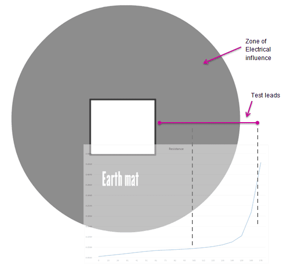
Getting the leads outside this area is so that the measurement is in respect to remote earth … otherwise, if the leads remain within the area of influence you are testing with respect to the area of influence, which would give you an artificially lower reading than the actual real value – a type of false positive, if you will.
Having a low reading is good, right?
The lower the impedance, the lower the EPR (earth potential rise) during a fault, so the safer the earth system is … this is true!
However, when there’s not enough land to deploy to a sufficient distance. Or the lead distances are too short due to lack of understanding. It’s all too common a mistake in the ‘real-world’ to accept the low FoP reading. When in fact the ‘actual’ true impedance might be many times higher than the value recorded.
This leads people into a false sense of security thinking a low FoP has been achieved when in reality the truth is anything but … and a genuine hazardous condition exists because the EPR is higher due to a higher earth impedance from the system.
When Virtual beats Actual
Simulation techniques using Electromagnetic Theory software tools, like the Hi-Freq module of CDEGS take previously unsolvable physical constraints out of the equation … there is now no excuse not to verify an earth system accurately to ensure safe operation (according to EIC EN50522 or EN50122-1).
There is one key point to bear in mind – this methodology is only valid using software based in Electromagnetic Theory … Circuit Theory based versions of CDEGS, such as MALZ or MALT cannot perform these simulations.
So what should you ‘take-away’ from this?
It’s one thing to do an on-site test, but getting technically secure results is no-so-straight forward, especially in built-up areas. By modelling and replicating the physical test procedure in the virtual environment. You can confirm that the test results are as they should be. Even when you can’t perform a full-scale test.
The science works … and works well! Why not drop us a line with your challenge on the chat line below …
[wptab name=’Author’]
 Ian Griffiths
Ian is a Principal Consultant at GreyMatters, with 26 years experience solving HV earthing, EMC, and lightning problems for clients worldwide. When he’s not busy studying problems and designing solutions. You can find him mountain biking, sailing and racing motorbikes in the summer. In the winter he tends to head off to the mountains chasing the snow with friends and family. Ian holds a Master’s Degree, and Degrees in both Mechanical and Electrical disciplines, and is one of the top 1% accredited CDEGS consultants and advisor to international utility companies, data-centre and infrastructure developers globally.
[/wptab]
[wptab name=’Latest Posts’]
Recent Posts by Ian
50 Shades Darker – CDEGS Myths Busted!
Real people, real answers in real time – the power of LIVE CHAT for our clients
GreyMatters – Protecting 100,000 lives through Earthing Design
[/wptab]
[wptab name=’Co-Author ‘]
 Hugh Wren
Hugh is a Research Engineer at GreyMatters, joining in 2014. He graduated from the University of Bath, sponsored by the IET’s Power Academy scheme. Hugh has a strong technical background with National Grid working on T&D schemes at voltages from 132 kV to 400 kV. Outside of work, you can find him cycling and fly fishing, or backstage at various local amateur dramatic companies.
[/wptab]
[end_wptabset]