We take a look at soil resistivity and provide practical advice on what is ground soil resistivity, why we measure it and these common mistakes when Soil Resistivity Testing:
- Surface Layer Resolution
- Buried Interference
- Weak Signal
- Background Noise
- Erratic Readings
Ground Soil Resistivity
‘Soil‘ is the term used in Electrical Earthing Design to define the upper geology. Which is of particular interest to us when designing earthing or grounding systems. The soil is the local geology consisting of layers that are primarily composed of minerals. Mixed with at least some organic matter. Which differs from their parent materials in their texture, structure, consistency, colour, chemical, biological and other characteristics.
Geologists might refer to soil as the combination of ‘drift’ and/or bedrock. The layman might refer to Soil more as ‘dirt’ or ‘ground’ (not to be confused with the American term).
The soil is the loose covering of fine rock particles that covers the surface of the earth. The soil is the end product of the influence of the climate, relief (slope), organisms, parent materials (original minerals), and time. (http://en.wikipedia.org/wiki/Soil)
What is Resistivity?
Resistivity is one of the fundamental electrical properties given to a material. For Earthing System Design, this can relate to any or all of the components used in a power system, e.g. copper, steel, aluminium, lead, etc. So, this means EVERYTHING in the system has a ‘resistivity’ including the ‘Soil’ in which the Earthing System is buried.
Resistivity is the unit of measure by volume that indicates how much a given material will oppose (resist) the flow of current into it, e.g. its apparent resistivity by volume.
When you consider … “What is the role of an earth/ground is within an electrical power system?” It’s easy to see why Soil Resistivity and deriving an appropriate, accurate and reliable soil model is of capital importance.
What is Earth?
In Electrical terms, the purpose of an earthing/grounding system is to provide a safe path for the dissipation/flow of Fault Current (an unplanned release of energy), lightning strike, static discharge, EMI (ElectroMagnetic Interference), and control the resulting surface voltage(s) in order to provide safety of the personnel and machinery. These points enforce the importance of the earthing design in any high voltage (HV) project.
According to BS EN 50522-2010, Earth is defined as … “The conductive mass whose electric potential at any point is conventionally taken as zero.” Thus, an earth/ground system can be defined as … “A conductor or group of conductors in intimate contact with, and providing an electrical contact to earth.”
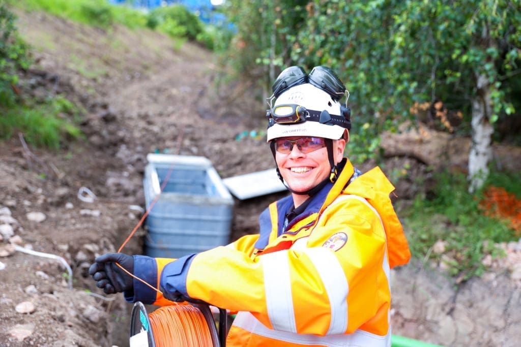
Soil Resistivity Testing
Soil Resistivity measurements are a critical foundational piece in the jigsaw of safe earthing system design. The results form the basis of all safety calculations. Therefore, it’s of capital importance to get the highest level of accuracy practical as many of the subsequent values of EPR (earth potential rise) and surface voltages are directly proportional to Soil Resistivity.
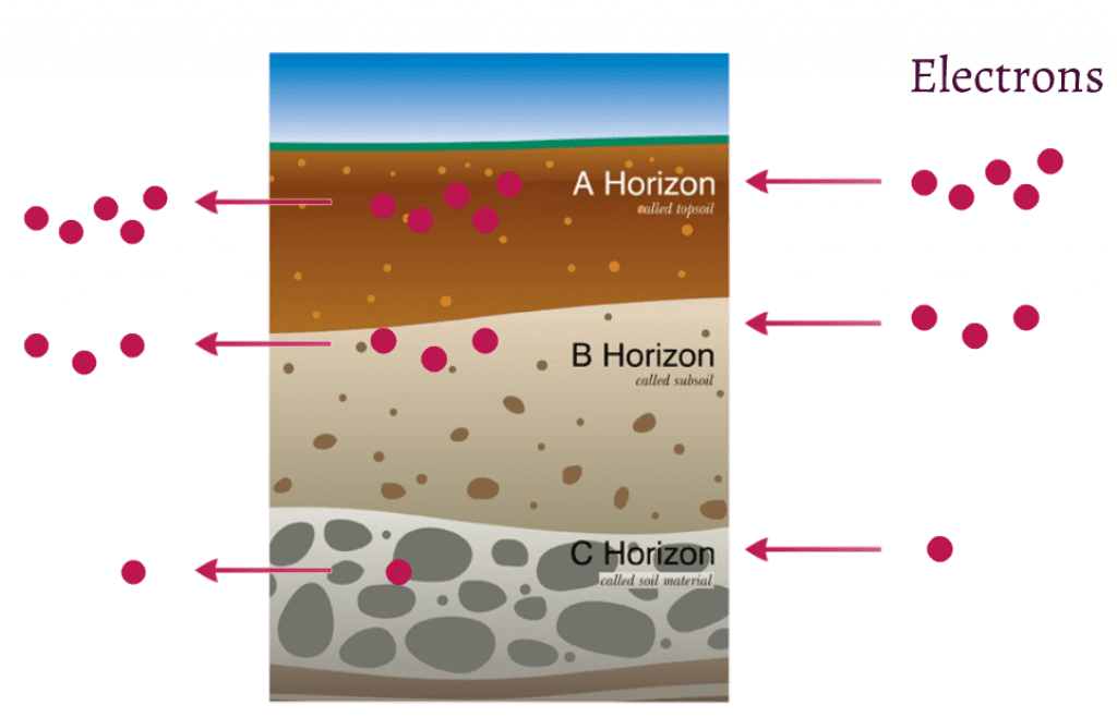
“Definition: a method of subsurface detection which measures changes in conductivity by passing electrical current through ground soils. This is generally a consequence of moisture content, and in this way, buried features can be detected by differential retention of groundwater. (hyperdictionary.com, 2013)
Ground Soil resistivity testing techniques have been used for many years for Geological investigations to locate bodies of water and/or other items of interest. In Electrical Earthing Design, the method is used to characterise the below-grade Soil Structure in terms of its electrical properties.
Why Measure Soil Resistivity?
The ‘Soil’ itself forms the very medium that any fault current will flow through. Therefore, understanding the electrical properties of the soil in which an earthing/grounding system is deployed is absolutely vital. Soil Resistivity constitutes the foundation for any electrical earthing design and cannot be understated. It is a primary component to all Electrical Safety Calculations. Such as, the permissible touch voltage calculations, the EPR (Earth Potential Rise), Hot Zone calculations, and individual system elements.
Soil Resistivity and the soil structure can have a massive effect on the complexity of the earth/ground grid design. The soil acts as part of the return path for the fault current to source. Higher soil resistivity will lead to a higher earth grid impedance value(s) leading to a higher Earth System grid voltage rise (Earth Rise Potential), which in turn gives rise to higher surface voltages across site. Surface voltages, if not controlled with appropriately positioned grading conductor design, could lead to an unsafe condition.
Every Electrical Power System design relies on understanding all the component parts (impedance’s) and Electrical Earthing Design is no different. The ground or soil is another component part in a circuit design… HOWEVER, whereas all the other constituent parts behaviour’s are well understood, e.g. the cables, transformers, generators, VT’s, CVT’s, etc. The soil on the other-hand, is a ‘natural’ semi-conductor. Which will have a unique set of electrical properties and be subject to infinite variability from site to site.
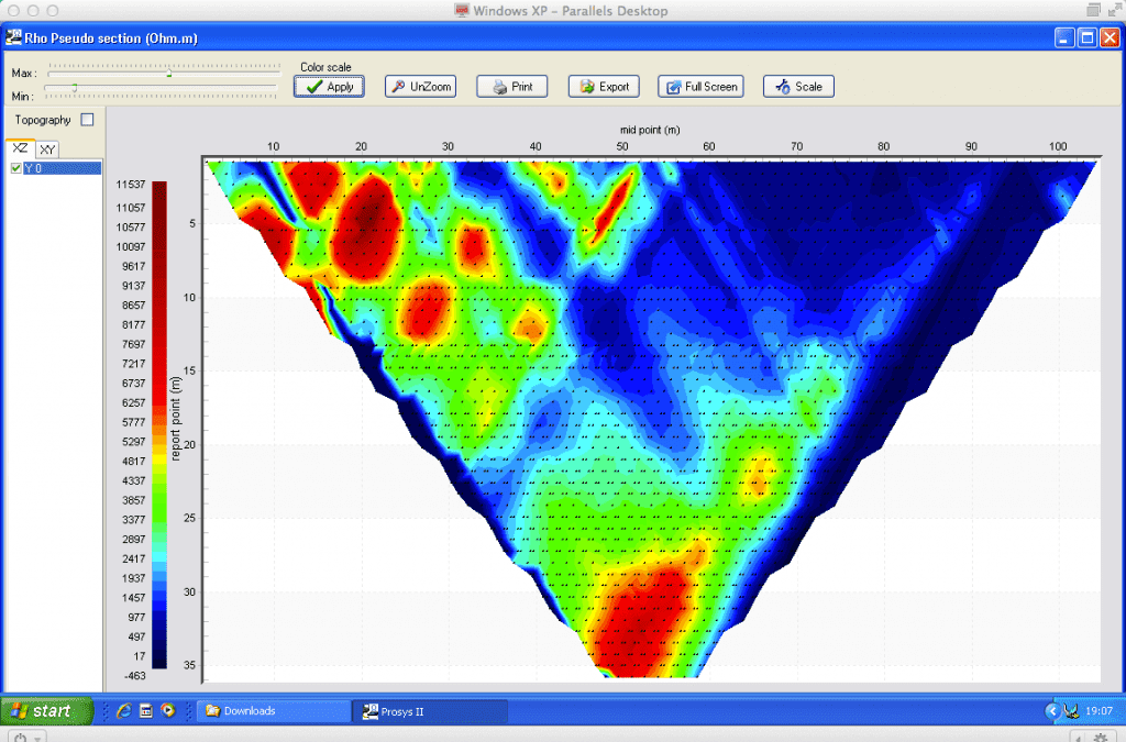
Soil Model
This set of unique properties are analysed and characterised into what is known as a ‘Soil Model’. This soil resistivity model can be made up of many layers going down to depths of many 10’s of meters in order to understand how much of the energy from a fault (an unplanned release of energy) will a) pass through into the soil, and b) for each layer, how much will enter and travel through each respective layer.
The amount of energy passing through each layer has a particular relevance when considering ‘Surface Voltages’ and the step and touch potential (voltage) safety calculations. For example, if the site has a LOW-ON-HIGH resistivity model, then more of the fault energy will prefer to travel in the upper layer. Whereas, a HIGH-ON-LOW would encounter the reverse. Where more of the Earth Return Current will prefer to travel in the lower layer. Both the example scenarios are important to understand when designing earthing arrangements to provide safety from the system.
#1 – Surface Layer Resolution
In short, not enough attention is paid to measurements being taken at the shorter distances during the soil Resistivity Testing (Wenner Method). This is not covered in any formal standard or code of practice, it’s just something that you pick-up with experience.
Short surface soil resistivity measurements in themselves are NO replacement for the full range of spacings required to provide the detail soil model for use in Electrical Earthing Design. But these soundings made within the first meter spacings are essential to determining the accuracy of subsequent wider measurements.
Without high resolution data during the first spacings, erroneous trending of the outputs can result.
#2 – Buried Interference
Soil Resistivity Testing Buried Interference can occur when, bare metallic structures (including concrete-encased metal) of significant length buried in the vicinity of the measurement traverse can distort Soil Resistivity Testing results.
When a measurement traverse runs parallel to a long structure of this type, significant error begins when the clearance between the traverse and the structure is on the same order as the electrode spacing. The error increases as the electrode spacing increases compared with the clearance.
A similar effect is observed when the electrodes are placed near relatively small grounding systems which are interconnected by means of overhead wires. As a rule of thumb, to avoid significant error, there should be no bare metallic structures of significant size buried within a radius r of any of the measurement electrodes. Where r is the spacing between adjacent current and potential electrodes.
When the measurement traverse runs perpendicular to a buried metallic structure without crossing it. The clearance requirement need not be as severe. Computer modelling of the buried structure and measurement electrodes can provide an estimate of the measurement error to be expected for different soil structure types.
#3 – Weak Signal
A Soil Resistivity Testing weak signal can result from a low-power source. A low-voltage source, or a high contact resistance of one or both of the current injection electrodes.
The problem is most often experienced when driving electrodes in high resistivity surface soils or when the electrode spacing becomes large (the signal strength is inversely proportional to the electrode spacing. For the Wenner 4-pin method, and inversely proportional to the square of the electrode spacing. For the Schlumberger 4-pin method, all other things being equal).
Use of a powerful, high-voltage source is an obvious first step to eliminating this problem.
Even with a good source, however, contact resistance can easily become a problem in high resistivity soils at the larger electrode spacings.
The solution in this case is to drive the current-injection electrodes as deep as possible and wet the soil around these electrodes with saltwater2. This should be done only for the larger electrode spacings.
If need be, multiple rods can be driven into the ground and connected together to constitute a larger, lower impedance electrode. On solid rock or in rock with a shallow soil layer over it. The electrodes can be driven into the ground almost horizontally or laid horizontally on the rock and covered with conductive material, such as salt water moistened earth.
If the rock is highly localised, then the electrode position can be altered (and noted) to avoid the rock. Interpretation from competent technical resources using software such as the RESAP module of the CDEGS software package will account for this.
#4 – Background Noise
Due to nearby sources of 50 Hz (or 60 Hz) current and its harmonics. Electrical noise at these frequencies is expected in the measurements, particularly for the larger electrode spacings.
Conventional measurement methods can confound this noise with the measurement signal. Resulting in apparent soil resistivity readings that can be an order of magnitude or more in excess of the true values. This suggests the need for equipment that uses a signal frequency other than 50 Hz and its harmonics and can efficiently discriminate between the signal filter and the background noise during Soil Resistivity Testing
A soil resistivity tester that has sufficient signal output and filtering is key when very large pin spacings or high resistivity surface material are expected.
#5 – Erratic Readings
So, when carrying out soil resistivity testing. Erratic readings can occur due to poor connections. Also, through high contact resistance. And background noise at a frequency similar to that used by the measurement equipment. Nearby buried metallic structures, equipment failure, operator error, and other factors.

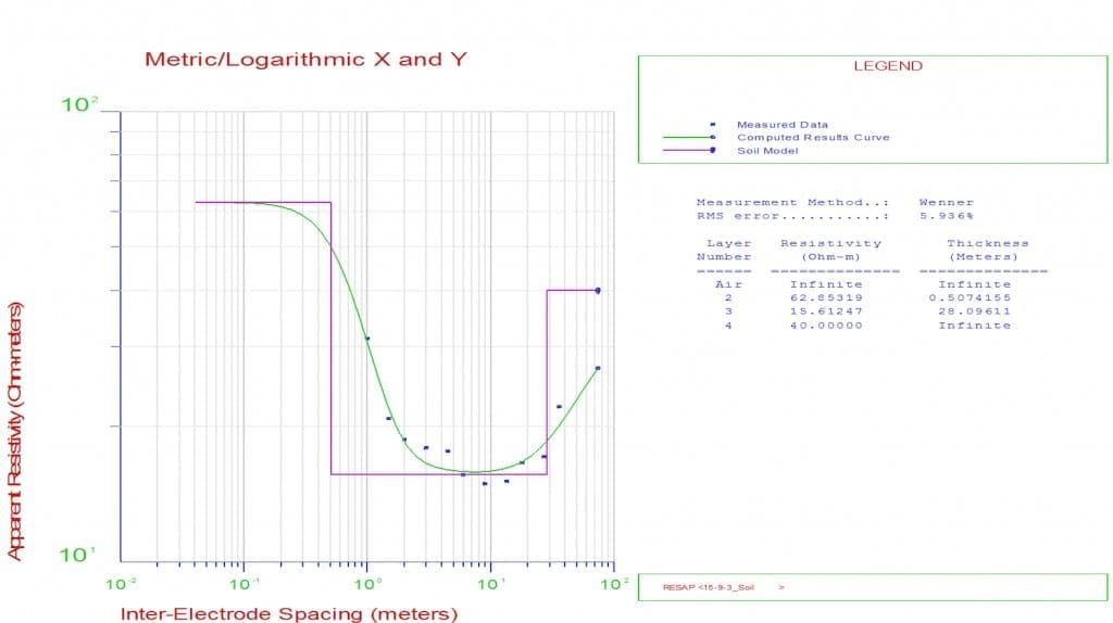
Therefore, ideally, after soil resistivity testing. Measured soil relativities plotted on log-log graph paper in the field, to permit detection of irregular measurements. Thus, eliminating erratic readings so, that corrective action can be taken immediately.
So plot soil resistivity readings, compared against electrode spacing. Also, expect a smooth curve. Sharp changes suggest a need for checking the equipment set-up. Therefore, repeating your measurements. Also, taking additional measurements at shorter and larger electrode spacings close to the problematic one.
- The Wenner and Schlumberger 4-pin methods differ only in the spacing of the two inner potential electrodes.
- Note that only the area in the vicinity of the current injection electrodes wetted in this way. This will not influence the measurements significantly. But, ensure that the wetted area is small, in comparison to the inter-electrode spacing.
Soil Resistivity Methods:
Engage with us…
- Earthing Design Services & Lightning Protection Design – If high voltage power systems and lightning are causing you concern why not see how we can help with a quick ‘live chat’ below as a start.
- XGSLab – A complete software tool for the simulation of Power, Earthing, Grounding and Lightning Systems, get in touch to request a free demo.
- Get Certified – Start your journey to become certified in Power Systems Earthing & Design.