What is ‘HOT-ZONE’ or ‘Hot-Site’?
There are so many misconceptions surrounding the whole concept of a‘Hot-Site’ and ‘Hot-Zoning’ for Electrical Earthing Designs. In this article, I attempt to simplify what ‘Hot Zone’ (or Hot Site) means in Power System terms AND crucially, explain what a ‘Hot Zone’ is not.
By the end of this article, you should hopefully understand that just because a site classified as a ‘Hot Site’. It does not mean it is necessarily unsafe.
Hot Site Basics – Earth Potential Rise (EPR)
If you know how an Earth Potential Rise (EPR) or Rise of Earth Potential (RoEP) occurs, then you can skip this bit. If not read on.
When a part of an Electrical Power System suffers a fault, it usually means there’s a short circuit somewhere. Often the short circuit can occur between one of the ‘phase conductors’ and the Earth. (To keep things simple, that’s the scenario we’re going to stick with here)
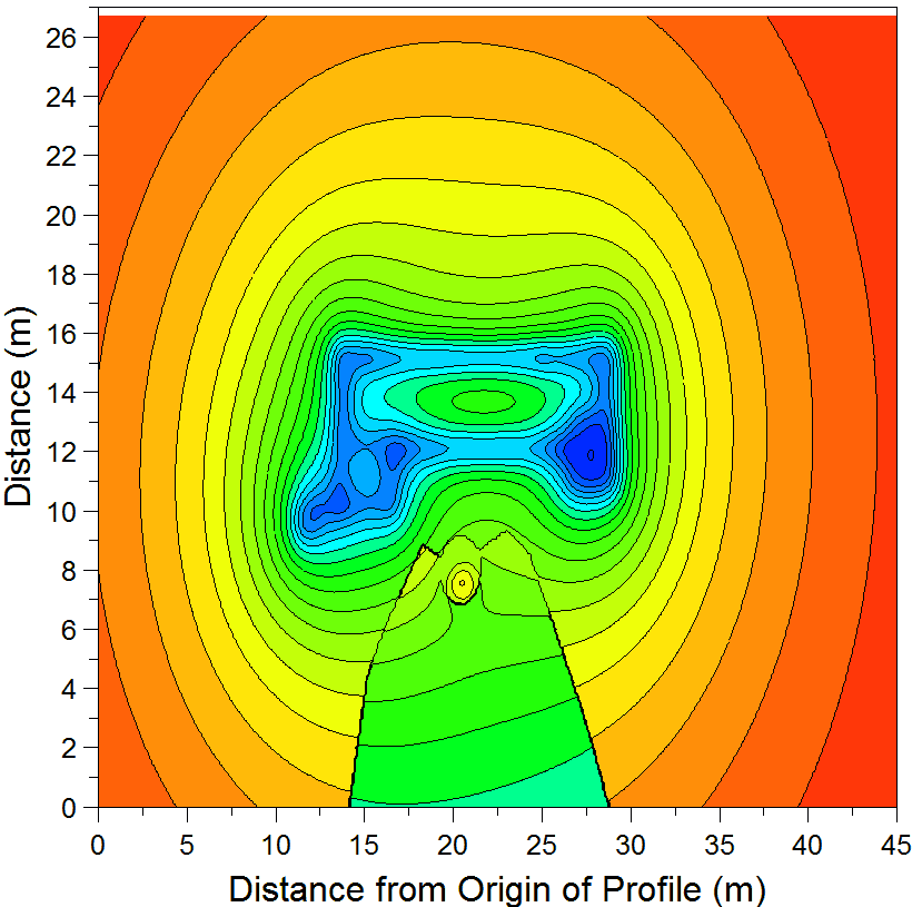
Take a minute and watch the video below. 26 seconds in, one of the phase conductors shown detaching itself from the supporting structure and dropping to the ground. What happens next is a representation of the Earth Potential Rise process, e.g. the energy inside the phase conductor released into the soil, and a rise in the surface voltage is created locally where the conductor dropped, which over time expands out across a given distance [In the video is it shown by colour contours bleeding/expanding across the site].
If you prefer a more physical analogy, it’s a bit like dropping a pebble into a pool of calm water. With the water analogy, the pebble has a store of kinetic energy (mass x velocity = KE). Which transfers into the water, creating ripples.
The more KE, the bigger the magnitude of the ripples. If we consider these ripples to equate to the electrical voltage contours of Earth Potential Rise (EPR). Then these will expand from the point of impact and extend out.
However, as the contours extend, so their magnitude decays with distance as the energy descends into the soil on its return journey back to its source (Earth Return). Therefore, most of the energy released will be present (momentarily at least) at the epicentre of the fault.
So, having explained a little bit about how and why the Earth Potential Rise takes place. We can move on to defining the term ‘Hot Zone’…
‘HOT-ZONE’ – What does it mean?
The Hot Zone or Electrical Hot Earth defined as the Earth Potential Rise (EPR) which extends in a radius from any bonded metalwork to the site’s Electrical Earth Electrode System or Main Earthing System (MES) that exceeds a magic number of volts. This ‘magical’ number of volts determined by the relevant national authority for each country. It will vary from country to country – but the principle remains once the EPR magnitude exceeds the threshold voltage, the sites now defined as being ‘Hot’.
The extent and shape of this ‘hot’ surface-voltage contour known as the ‘Hot Zone’. In the States, this Hot threshold set at 300 V. But for the IEC based countries, the picture gets a little more confusing…
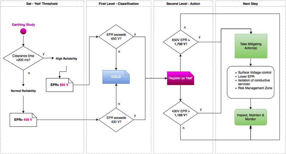
EA TS 36 – when is a site Hot or Cold?
For European and IEC based countries, the magnitude used to define this ‘Hot’ threshold subjected to the site’s protection settings (clearance times).
For example, a site that can clear a given fault reliably and quickly (e.g. within 200 ms) can behave a higher EPR before it falls into the classification of being ‘Hot’ than say, another site that clears its faults in much longer times, say, 1 second for argument’s sake.
The concept of defining ‘high reliability’ vs ‘normal reliability’ is hugely relevant. After all, a high-reliability site will be able to restrict the amount of energy released before isolation much more efficiently compared with those sites that do not have the same level of control or protection.
This level of protection is why the high-reliability sites have ‘Hot’ voltage threshold than the regular reliability sites. Given the resulting hazard from touch and step voltages are proportionally lower for sites with a quicker clearance time (protection).
In the UK, the Hot Zone historically measured as anywhere within 100 m of the boundary of the high voltage compound at a Hot Site. However, since 2007 it is allowable to use the Energy Networks Association (ENA) Recommendation S34 – A Guide for Assessing the Rise of Earth Potential at Substation Sites, to calculate the Hot Zone. This guideline currently defined as a contour line marking where the Rise of Earth Potential (ROEP) exceeds 430V for regular reliability power lines or 650V for high-reliability lines.
So, you’ve got a site that’s classified ‘Hot Site’ – now what?

Don’t panic! The Hot/Cold classification is simply part of a formal Risk Management process that allows the asset owner to register the site as a ‘hot site’ and inform other parties that a hazard ‘may’ exist – A sort of red flag or indicator.
If a site defined as a Hot Site, it’s ‘Zone’ (extent) will also need to be calculated. Software tools like CDEGS widely accepted as the preferred method/tool of choice to establish the Hot Zone contour(s).
In some circumstances (such as when a ‘cold’ site upgraded to ‘hot’ status), the Hot Zone may take in residential or commercial property which is not within the property of the site’s owner. In these cases, an assessment needs to establish if the Hot Zone EPR exceeds a second ‘actionable’ level.
The second ‘actionable’ level defined as the contour line marking where the Rise of Earth Potential (ROEP) that exceeds 1,150 V for standard reliability protection and 1,700 V for high-reliability systems, confused?
Don’t be, Noise regulations in the EU follow a similar approach. For example, the Noise at Work Regs has a lower (80 dB) and upper exposure action value (85 dB) for the lower level, guidance that’s all it needs; it’s when reaching the higher threshold that controls are mandatory, and the Hot Zone principle adopts a similar methodology as below table lays out.
| Normal Reliability | High Reliability | What to do | |
| First level EPR value | 430 V | 650 V | Enter site details on the national register |
| Second level EPR Value | 1,150 V | 1,700 V | Action Controls/mitigation |
What does ‘Hot’ NOT mean?
It is a common misconception to think that just because a site has an EPR that exceeds the first level (430 V or 650 V), as Energy Networks Association (ENA) Recommendation S34 that the site is unsafe to enter or to work inside this zone. This recommendation, by itself, is not the case.
When a substation or site classified as ‘hot’ within the first action level, it is providing a management trigger for Risk Management measures to be considered… It’s when it exceeds the SECOND action level that then controls measures required to mitigate.
Let me repeat that! – Just because a site has reached level 1, the ‘Hot’ classification does not mean that mitigation measures are automatically required. Since 2007 under S34, mitigation required when the second action level gets exceeded.
What do Hot Zone control measures look like?
Control Measures may include several actions depending on configuration, and these include (not exhaustive):
- Appropriately designed Earthing arrangements to satisfy permissible touch & step safety voltage thresholds
- Ensure sufficient maintenance and inspection
- Isolation of incoming/out-going telecommunications cabling
- Informing 3rd parties as appropriate
Maybe we will explore the control measures in a subsequent blog.
This principle is probably one of the more misunderstood concepts within Electrical Earthing Design, so reach out via live chat or contact us to access a bit more GreyMatter on the subject and we can demystify a little more.