
During a recent training event held by SES Technologies for CDEGS (Current Distribution, Electromagnetic Fields, Grounding and Soil Structure Analysis). A finite element analysis software suite for Electrical Earthing System Design, a number of issues were discussed. But one that crops up time and time again in the UK was that old chestnut in Electrical Earthing System Design Separation.
What is Electrical Earthing System Design Seperation?
In electrical earthing systems, separation refers to the physical distance between different parts of the earthing system. Such as the main earthing system and the electrical equipment being protected. This separation is important to ensure that any electrical fault or surge is directed to the earthing system rather than the equipment. Reducing the risk of damage or fire. The specific separation distance will depend on the type of equipment and the local electrical codes and regulations.
Electrical Separation in Earthing System Design
In the UK, it is often assumed that a separation of 10m between earths will prevent the transfer of potentials between the two electrical earthing systems. For example from the primary to the secondary. Therefore we often encounter sites which have separate HV and LV earths. The discussion we had showed that in many situations, this would not be the case.
The concept of separation works by creating a high resistance (Ohms) between the earths. Unfortunately, separating the Earth Mats by a distance (metres) does not always work. This ignores the soil resistivity (Ohms times metres). The resistance is affected by both the distance AND the resistivity together.
“electrical earthing separation (that is dictated by conduction in the soil) will depend heavily on the type of soil structure that exists at the ground site” S Tee and F Dawalibi, 2003
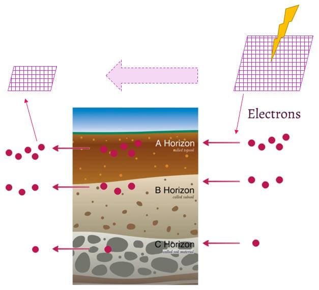
Soil Resistivity
This highlights the importance of acquiring good data on-site to support the Soil Resistivity side of the equation. And accurate modelling to determine the optimal earthing system design. Where a properly designed earth already exists, formal bonding will not introduce a new hazard. But by attempting to separate the earths, a new and largely unpredictable hazard is created. As the likelihood of potential transfer ‘through the soil’ is uncertain to say the least.
Want to know why soil resistivity testing is important to safe electrical earthing design? find out here.
Example 1 in Electrical Separation in Earthing
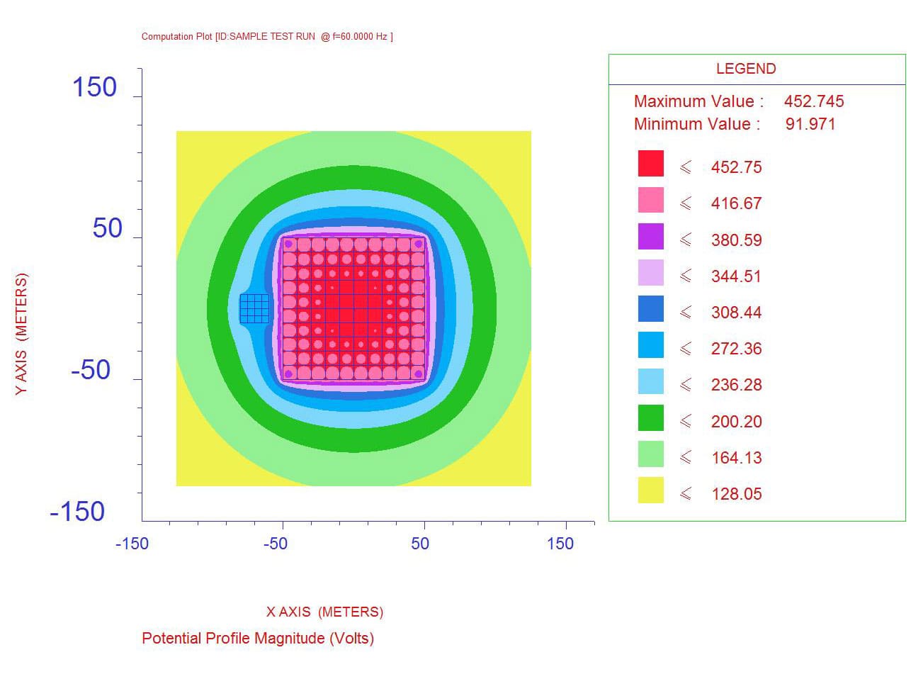
The first example, below shows a large substation site, with a small site next to it. Perhaps a telecoms mast or small substation. They are located in 100 Ohm’s homogenous soil. The plot demonstrates that although they are physically ‘separated’ by 10m; the isolated earth mat still rises to 60% of the voltage of the substation earth mat.
Example 2
As we often discuss with our clients, a voltage of and in itself is not a problem. The lack of awareness as to its level, and whether it introduces a touch voltage hazard, could lead to death or serious injury.
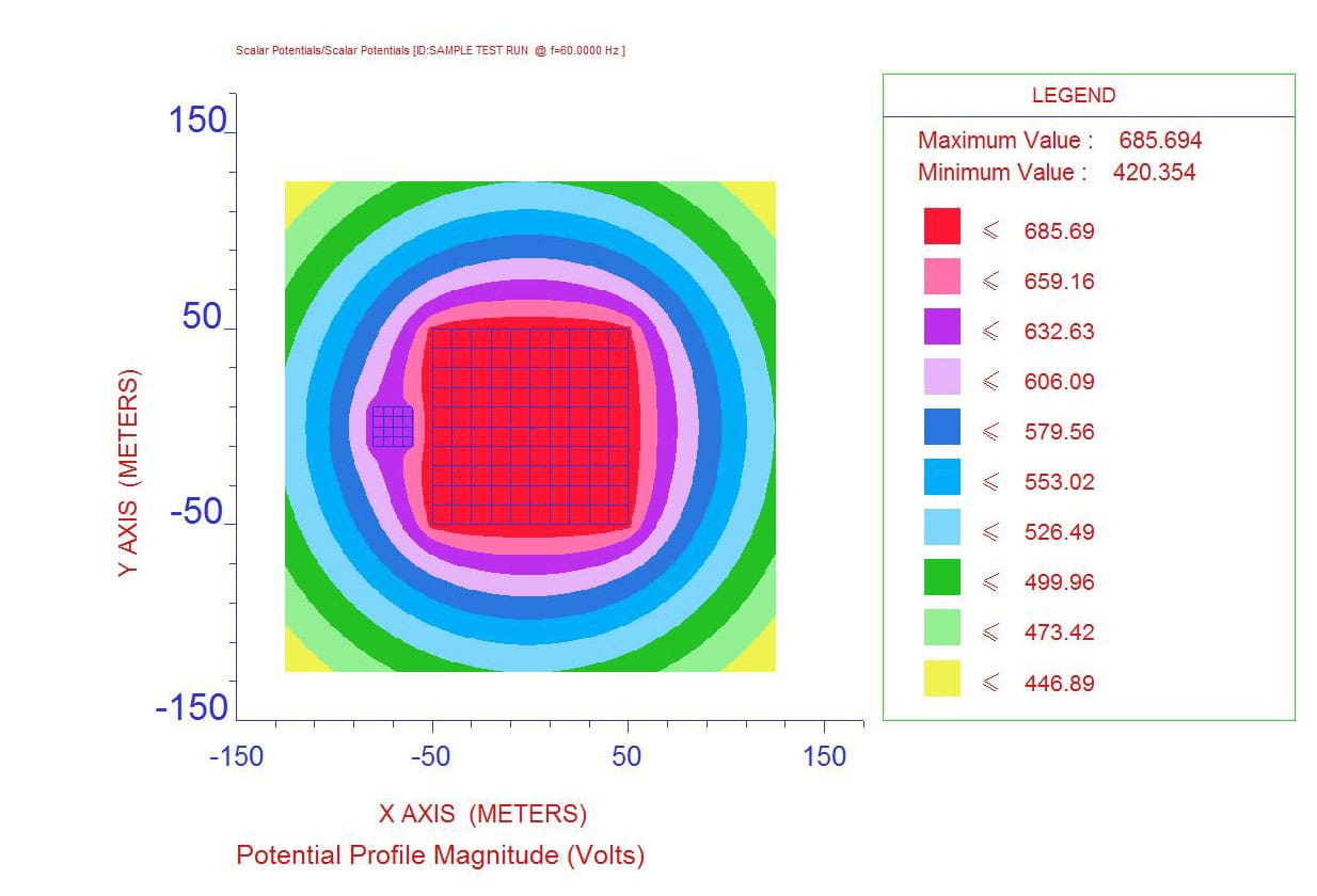
A more extreme example is examined, where the soil structure is changed to a two-layer 10 Ohm.m upon a 1,000 Ohm.m layer. In this situation, the currents circulate in the top layer of soil. As a result, the difference in voltage between the 2 grids is very low, and the smaller grid rises to 92% of the voltage of the faulted substation grid, as shown below.
This issue is further complicated by the need to maintain isolation. Take the scenario where the smaller Earth is a telecoms mast required for the protection on the main substation. This would imply data lines being run into the substation control room. Ensuring isolation during installation is possible. But ensuring it is maintained during future works for the life of the substation, which may be 50+ years, is very difficult.
Global Earthing
So, don’t make the mistake of assuming that separation works as a policy. We’ve shown that in a very normal environment, a faulted Earth System can transfer more than 60% of its voltage through the soil to another local earth. This is why a Global Earthing approach is default policy of choice in many developed countries. It’s safer and much more robust. If you believe your current Electrical Earthing System Design needs a rethink from some new GreyMatter then get in touch and we can discuss your challenge.
Featured Image: Tinker Rasor
Engage with us…
- Earthing Design Services & Lightning Protection Design – If high voltage power systems and lightning are causing you concern why not see how we can help with a quick ‘live chat’ below as a start.
- XGSLab – A complete software tool for the simulation of Power, Earthing, Grounding and Lightning Systems, get in touch to request a free demo.
- Get Certified – Start your journey to become certified in Power Systems Earthing & Design.