
Ground testing is typically performed in two stages. The first is conducted during the construction of a building to ensure proper installation of the electrical system. The second involves routine ground testing to ensure the ‘actual’ arrangements perform as ‘predicted’ at the design stage, thus avoiding costly and fatal errors.
What is the Difference between Grounding and Bonding?
Grounding, also known as earthing in the Commonwealth countries, ensures that the electricity travels through a low-resistance path. When it flows from the source. And returns through the neutral connection. For the most part, the ground (or earth) connection acts as a secondary path for electrical safety. By ensuring that the return path is sufficient to keep the EPR (Earth Potential Rise) within the permissible levels. On the HV systems.
Bonding usually refers to the formal above-ground conductive connections and in an electrical system while grounding (earthing) is s anything below ground i.e. the electrode that provides part of the protection system for electrical equipment. The ground fault circuit designed to protect individuals by ensuring electrical safety. Therefore all the electrical components are bonded to the circuit breaker. Similarly, bonding will not ensure protection without grounding/earthing.
Why Electrical Grounding Fails and how in ground testing
Bonds or connections tend to become loose over time (unless welded). If the wrong materials are used during the initial connection, they, too, can eventually fail. Corrosion can deteriorate the ground rods and connectors. In certain cases, minerals and chemicals may be present in the soil, which can dissolve the electrode over time. A pH range of 6-10 is generally not considered hostile to copper.
Equipment grounding also works to reduce dangerous sparking due to ‘impressed voltages’ on metals that are in close proximity to power lines and distribution equipment. Other important functions include:
-
- Controlling and manipulating surface voltages to prevent hazardous touch and step voltages (stress voltages).
-
- Providing functional earth for equipment to work properly.
-
- Mitigating against EMI (electromagnetic interference).
This keeps damage from arcing within structures and any equipment that has the potential for buildup. Bonding and grounding help drain the static buildup that can happen on piping, tanks and vessels before they reach their flashover potential.
Electrical power systems are grounded to restrict the voltage that is induced by surges, lightning, or unintended contact from high-voltage lines. Secondary grounding also stabilizes the return path of all single-phase loads and ensures safe dissipation.
Moist soil usually has better conductive properties than dry which means good electrical geo-connection and low resistance but if it contains sand, rocks and clay, the resistance usually increases. Wet and dry cycles also create air gaps in the soil, disrupting the contact with covered electrodes. Seismic activity, vibration, fluctuating water-tables, and sand migration are other factors responsible for changed contact resistance.
The catastrophic consequences of improper grounding
Not having a failsafe ground or earth testing system in place can invite expensive equipment replacements and lead to loss of mission-critical data. It also puts both life and property at risk. When vital equipment is left without adequate grounding and bonding, it can experience damaging voltage surges and spikes.
Alternating failures can also invite problems from random shocks that leave equipment out of order. Such failures are also difficult to diagnose because the actual cause of failure is in fact, lack of ground testing. For instance, when random shocks were experienced in the shower area of a fire station, extensive testing revealed that a part of the structure was operating like a capacitor. This happened because of static electricity buildup and without adequate grounding and bonding; the electricity was discharged through an individual. This problem was intermittent as the energy buildup took time to reach to a discharge point. However, these micro-shocks are rarely dangerous and can be a common-place in HV substations (132kV-400kV) where the impressed voltages in steady-state are so high that any resistance in joints (no matter how small) sets up the micro-shock. But, all of this could have easily been avoided with regular electrical maintenance.
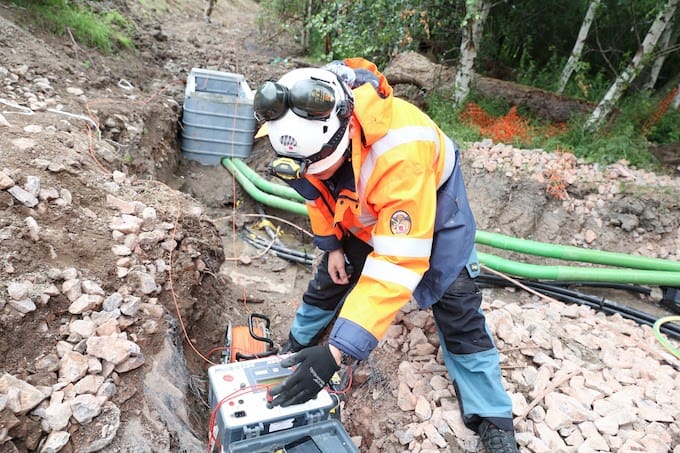
Types of Ground testing and Their Uses
Ground testers can be classified into two main categories: clamp testers and multi-pole ground testers. These testers actually inject a small (20-50mA) signal current at a given voltage and then measure the returning voltage. Then, they apply ‘Ohm’s to convert the voltage registered into a resistance value to display. These testers can be safely employed for taking different measurements including:
-
- Insulation resistance
-
- Ground bond
-
- Earth Leakage
-
- Grounding (or Earthing) resistance
-
- Earth continuity
Grounding (or earth) resistance testers are designed for use in construction and telecommunication projects.
Clamp-on testers have advanced filtering and separate transformers for both source and measurement. The source transformer applies voltage on the loop that is being tested and the measurement transformer tracks the resulting current while the filter identifies its own current and screens out the remaining signals.
Clamp-on testers can also measure earth ground loop resistance inside residential buildings, industrial locations and on power towers. They can perform certain functions that normal testers find inconvenient but their accuracy rarely matches the direct measurement of conventional testers.
The ultimate goal of most ground testing is to ensure the lowest resistance value as it enhances electrical safety and also makes sense economically. For this reason, it should be made a part of periodic electrical maintenance. The exception is on high resistance earth systems, such as those found in mines and quarries where low resistance systems are hard to achieve and even harder to maintain their integrity due to the constantly changing operating environment.
Engage with us…
- Earthing Design Services & Lightning Protection Design – If high voltage power systems and lightning are causing you concern why not see how we can help with a quick ‘live chat’ below as a start.
- XGSLab - A complete software tool for the simulation of Power, Earthing, Grounding and Lightning Systems, get in touch to request a free demo.
- Get Certified – Start your journey to become certified in Power Systems Earthing & Design.