Are you responsible for carrying out or coordinating Soil Resistivity testing?
Learn how to avoid 7 common mistakes when testing and what IEC BS EN 50522 says about soil resistivity testing. We share some tips and trickes to make your life easier and error-free. Click here to watch the full webinar replay and learn how to avoid common mistakes.
What is Soil Resistivity Testing?
Soil resistivity testing is a method of measuring the electrical resistance of soil. It is commonly used to determine the suitability of soil for various purposes, such as earthing (grounding) systems in electrical engineering, and to design foundations for buildings and other structures. The resistance of soil is affected by various factors, including its composition, moisture content, and temperature.
To perform soil resistivity testing, a set of electrodes is driven into the ground at a specific distance apart, and a current is passed through the soil between the electrodes. The voltage that is measured across the electrodes is used to calculate the soil resistivity. The lower the soil resistivity, the better the soil is at conducting electricity.
Soil resistivity testing is often performed using specialized equipment, such as a four-point probe or a Wenner array.
Soil Resistivity Webinar…
Ian: Okay. Hi, guys. Thanks for taking the time out to be here today. There’s a slight departure from our normal format in that Hugh and I are disappearing off into Northern Europe to do some soil resistivity testing. Which is quite ironic as this is the topic that we’re covering today.
So soil resistivity’s one of the most highly requested topics on our webinar series. So without further ado, I’m going to now pass you over to Hugh who’s going to take you through things, and hopefully, we’ll see you on the other side. All right. Hugh, over to you.
Soil Resistivity Testing – Tips & Common Pitfalls
Hugh: Thanks, Ian. I’m just going to share some quick slides. We will spend about 20 minutes talking about some tips and I’m going to offer up some common pitfalls people fall into when they’re doing soil resistivity testing.
So I’m going to give you a quick introduction. I’m then going to dip into what the European standard for Earthing says about soil resistivity testing. I’m going to talk about some common mistakes. And I’m also going to show you some of the tools GreyMatters use to remove sources of error in our testing. And then after that, we’re going to open up to questions and talk about the next steps.
Soil Resistivity Measurements
So, soil resistivity measurements are one of the most important things when you’re doing your earthing model. It’s one of the biggest sources of error, where you get it wrong. It really changes the outcome of the modelling process. It’s really important that you get it right. I’m going to show you some of the common places where it goes wrong and just quickly highlight some of the things we use that make our lives easier and improve the quality of our measurements.
I’ve just taken a couple of snippets from BS EN 50522. This is from annexe NC, so that’s only available in the British Standard version. If you don’t have the British Standard version, you won’t be able to find it. But it just highlights, again, that the soil resistivity measurements are critical to determining the optimal earthing design. It then shows you the recommended test set-up and gives you some suggested spacings. And we’ll come back to these in a minute. But you can see that to meet the requirements that you actually need quite a lot of space to do the testing, and that’ll become important later.
7 Common Soil Resistivity Testing Mistakes
These are the seven biggest factors in getting soil resistivity measurements wrong:
- Inter-lead coupling
- Buried conductive structure
- Traverse distances
- Background noise
- Instrument error
- Poor connections
- Leaving site before checking the data
1. Inter-lead coupling
So, inter-lead coupling can have a really strong effect.
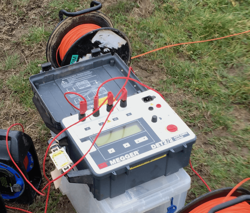
Now, if you use a traditional earth tester, like DET2 or the Arnoux 6470. They use quite a high test frequency of about 128 Hz, and because of that, you get coupling between the test leads. So the cable you’re sending the current down induces a voltage on the cable that’s measuring the voltage. And the consequence of that is that you get a noise signal that’s potentially bigger than the voltage signal you’re trying to measure from the soil. And that’s a noise signal that might become a problem.
Instead, you can use a tester that produces a DC signal which then doesn’t introduce the same problem.
2. Buried conductive structures
Another really important one is looking at the buried conductive services. So, when you measure the soil resistivity, you’re measuring the resistivity of all the things in the ground underneath you.
Generally, if you’ve got a big metal pipe there, that metal pipe is going to be a whole lot lower resistivity than the surrounding material. So it’s really important when you’re doing your measurements to use a CAT and Genny or something else to find these buried services and avoid them.
Also, when you’re planning measurements, to look out in advance and use the freely available utility drawings that you can get your hands on.
Now, because these buried services mean you often get an overly low result. That can seriously affect your calculations because it means you end up with much less earthing than you actually need. And then when you come back to your testing at the end of the project, that’s going to have a really big impact on rework. Which will be very expensive.
3. Traverse distances
Now, traverse distances are quite important because you want to characterise the biggest volume of soil possible. So, getting a lot of data in the top 5 or so metres is really important.
But the electrons, they’re going to travel through a much deeper section of the soil, potentially up to 50 or even 100 metres down when you’ve got a really large earth map. So you want to know that not only what the resistivity of the soil your earth electrode is in is going to be but also the resistivity of the soil underneath your earth electrodes. Because if your electrons can only travel in a little 2-metre-deep band of soil at the top, then that’s going to present a much higher resistance to the electron travel. Compared to a situation where you’ve got lots of nice low resistivity soil for maybe 50 or 100 metres.
Now, the BS EN 50522 says you should you use an a-spacing of up to 100 metres. Which means that you need 300 metres of linear space to do that measurement, and actually, in a lot of scenarios, that’s just not possible.
We tend to go for a maximum a-spacing of 54 metres because that tends to be achievable on 9/10 sites we work on. And the key things is, you deploy your leads as far as you practically can. And sometimes that means you need to take measurements a little bit off-site. Maybe look at going into a public park or identifying another potential location to do the test as well as on the site where you’re building your earth system.
4. Background noise – in ground
This is another one which can be a little bit hard to predict.
Now, there’s always going to be a little bit of electric energy floating about in the soil. Just because of the nature of our interconnected world. Most of the time, that’s not going to be a problem, but sometimes you get really big electrical signals in the soil that, again, completely dominate the testing your tester’s putting out.
A key one is something like cathodic protection on long pipelines. But there can be all sorts of things that come in here, and I could spend days just focusing on this area.
So, to avoid this problem, tester signal strength is key. And, again, planning is key because you want to be able to predict as many of these sources of in-ground noise as you can. It’s also worth noting that when in-ground noise is really high, that can cause a safety issue because that can be coupled onto the copper test probes, you’ve driven into the soil.
Ian: Some of the in-ground noise or sources of in-ground noise can be natural as well. For example, there are certain geologies that seem to emit the noise as an in-ground noise source. So there are particular places in the world which are notorious for this, especially where granite is concerned. But I don’t want to steal your thunder, Hugh.
Hugh: No worries. No, that’s an important point there, Ian.
Background noise – above ground
So then we’re going to look on to above-ground background noise.
Now, the big thing here is going to be overhead power lines. Where you’ve got potentially thousands of amps flowing through each phase conductor. Especially on the large high-voltage power lines, of course. But if you deploy your test leads parallel to these power lines, again, as we talked about with the test lead induction, you get induction from the power lines. And the field associated with these can be significantly bigger.
It’s another thing that can also be dangerous. If you’ve got a couple of hundred metres of test lead in parallel with a power line, that could pick up quite a high voltage which might cause there to be a high voltage on the test probes. And, obviously, you get the high voltage on the measurement leads which means that your measurements are wrong. Also, it’s putting your guys doing the testing into danger.
And, here, the only thing you can do is to move away from the power lines. Now, if that’s really not possible, you can do your measurements at 90 degrees to the power lines, and that takes away the coupling. But it’s worth noting that we normally do two traverses that are perpendicular to each other. That’s a really useful thing to do because it means that it cancels out some of these other problems. And obviously, you can’t do that if you’re only able to do your test perpendicular to the power lines.
5. Instrument error
Another one’s instrument error. And obviously, getting your calibration done is very important, and certain instruments will fall out of calibration.
But also, if your tester doesn’t put out a strong enough signal to fully characterise the material it’s measuring, you’ll get overly low results. Potentially, you won’t find out about this until you process the data.
I’ve done a couple of measurements in the field with a DET2. And after a few hundred ohm-metres, I’ve found that a DET2 tends to under-measure on soil resistivity. And that can be absolutely catastrophic. If you’re lucky, you’ll find out about it when you do your data processing, and you compare it to what you were perhaps expecting to get, and you find it’s lower. Or if you’re really unlucky, you don’t find out about it until you’ve built it and you do your measurements. You then find out your design hasn’t worked out. And then you’ve got a big problem there.
6. Poor connections
Now, poor connections are a common hazard when you’re walking up and down in cornfields, trying to set up your test. Because it’s quite easy to lose sight of where your test leads are and where your clips are.
So, it’s always worth double-checking that everything’s connected up properly. That the connections are going to the right place on the tester. That there’s a good connection from the tester all the way through to your probe and particularly, on the current leads, that there’s a good connection from the probe to the surrounding material. So sometimes you might find you need to add multiple probes on the current injections and, perhaps, even drive the probes deeper.
Multiple-probe array
Ian: So another thing that Hugh mentioned to minimise the error is multiple probes.
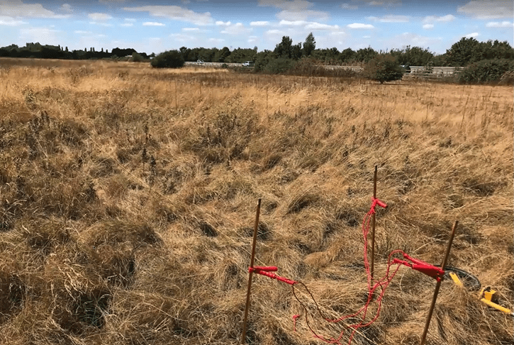
So, this is what a multiple-probe array might look like. It’s nothing special, but you can see that we’ve got an arrangement here of three electrodes which are all interconnected. And this is on a long traverse, so this could be a 100-metre traverse or something like that. So the fact that you’ve gone a little bit further out by sort of 3 to 400 mm doesn’t make any difference. But you get much more connection with the geology, a better electrical influence. So that’s just an example of what multiple-probe array might look like.
Hugh: You can look at things like adding a bit of bentonite to get good connectivity from your test probe to a soil that contains large particles. For example, if you’re doing testing on something like crushed granite.
And finally, you can look at re-siting the probe somewhat. If you move the test probe 500 mm, that’s not going to cause a huge amount of inaccuracy in the results compared to the inaccuracy of not having a good connection to the surrounding material.
7. Leaving site before checking data
Now, the other really important thing is to sense-check your data before you leave the site.
If you plot your graphs and look at them and check they make sense before you leave the site. If you identify there’s a couple of data points that have gone a bit awry, you can go back and redo the testing while you’re there, while you’ve still got the equipment set up. And then you can just rule out any errors where things don’t quite look right.
Obviously, it’s much more expensive to have to go back to site a second time. Especially if you’re going to a site in another country.
What we’ve encountered
Now, there’s a couple of other little things that we’ve come across.
In very damp soil, you can find that the testers behave quite oddly. Obviously, if the soil’s very damp and it’s not normally very damp, you might find that your measurement’s much lower than what you’d expect. So we tend to recommend avoiding testing after heavy rain to avoid this.
And one that was a really big headscratcher on a project was when we did a project near the sea. We managed, completely by fluke, to do our test measurements at high tide where the water table was really high. So consequently, the resistivities we measured were much lower than what would be found at low tide where the groundwater is much further away.
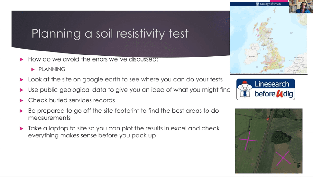
Planning a soil resistivity test
So how do we avoid these errors? Well, there’s the famous six Ps which really should just say planning, planning, planning, planning, planning.
The key thing is to use the technology we have to find out as much as you can about the site before you go there. Have a look on Google Earth or Bing Maps or whatever your mapping service of choice is and identify some areas where you think you might be able to do the test.
There’s also Linesearch before you dig which gives you access to all the utilities, buried services records so that you can identify if there’s going to be any buried services that are near your test areas and help you to avoid them.
Now, a thing that’s a little bit counterintuitive is to be prepared to go off the site footprints to find the best areas to do the test. Because often sites are quite congested, you can’t maybe deploy your test leads to the full distance. You’ll likely find there’s quite a lot of buried services if the site’s already active. So you’re unlikely to get the best test results in a congested building site. So maybe you might find there’s a completely clear farmer’s field next door that you can perhaps do your test on or there’s a public park.
And by planning your test locations in advance, you can easily identify where these alternative locations might be. And if you need to reach out to landowners beforehand, then you can do that from the comfort of your office instead of being chased off by a farmer with his salt pellets.
Ian: Yeah, I think it’s a good point there, Hugh. And the goal is to look for a section of undisturbed land which on construction sites is always a challenge. What we’re looking at doing is getting a representative idea of the geology in the area.
Now, typically, you can look at a location that might be 250 metres away, but you’re looking for that undisturbed piece of land that you can get some good quality data. That will be representative of the footprint that the site is going to be placed in.
Another interesting point that you put up on the slide there, Hugh, is you can see that those crosses of traverses that are set, hopefully, at 90 degrees to nullify any kind of in-ground noise effects or picking up of induced voltages. That’s a great example of what you’d typically look to achieve.
Hugh: Yeah. It’s worth pointing out that the little red box at the top of the picture is our site where the earth electrodes are going to be built. And here’s a good example of where doing the testing on the site footprint is quite problematic because we’re next to an active railway. So we’ve got these big conductive structures that are likely to affect our results. So on this one, it was really important to be further away from the railway to get the accurate results that we need to do the modelling.
And once again, take a laptop to site. Find some other way of being able to plot your results while you’re there, so you can see that there are no weird outliers, there’s nothing that looks wrong. Because when you’re doing these measurements, you’ve got to trust your gut. And if something looks wrong, there’s a good chance it is wrong.
Soil resistivity – Nordic Countries
A key thing that’s affected a number of projects we’ve worked on is really high soil resistivity which is quite common in the Nordic countries.
Often, there’s not much soil sat on top of the bedrock, so instead of driving piles through soft soil. They just clear the soil and blast through the bedrock to create a flat area to build on. Now, this is already problematic for earthing just because bedrock, and especially granite, can be very high resistivity. So, it’s really important that you have the right tester to measure the resistivity and to get that right.
How do we avoid some of these issues?
Well, we use a high-current earth tester. Our in-house, everyday tester’s Iris Syscal Junior, and we sometimes hire the higher-power versions of the tester where it’s necessary.
We also have our custom test leads which show us exactly where we’ve got to drive the probe in, so you don’t have to mess around with tape measures and trundle wheels while you’re out on site.
And finally, we use a Forms App for data capture.
Syscal Junior
So, the Syscal Junior is our dedicated soil resistivity test instrument. It only does that. And it outputs a test energy of about 100 Watts which is a whole lot more than a conventional instrument like a DET2 would do.
Secondly, instead of just doing one test, it can be set to do five or six tests, one after another, and it takes an average of those so that if you’ve got things like periodic in ground noise, where it’s on for a bit then off for a bit, you’ve got your best chance of avoiding – and also, it just means that if it does some error checking that flags up if there’s a problem with your test set-up.
Custom test leads
We also use these custom test leads.
Now, any test cables will be perfectly sufficient for doing a soil resistivity measurement, but when you’re doing it a lot and when you’re trying to do it quickly, having everything premeasured up, having the connections all in the right place where you need them makes the whole test process so much quicker. And it reduces the number of people you need onsite to do the work, and it makes things easier.
Mobile forms app
The other really interesting thing that we use is our mobile Forms App, and this is a really powerful tool that allows you to collect data from sites simply by tapping it in on your phone.
It collects an accurate location for every test you do, and there are no lost pieces of paper, the results get pushed up to the cloud immediately, and it means that we can review the results from our field technicians without them having to read out test results over the phone or just wait till they come back from site.
So, that’s a really powerful tool to really streamline your soil-resistivity-measurement process.
Review
Okay. So I showed you some of the common mistakes in the soil resistivity measurements, I showed you some of the tools we use to avoid these mistakes, avoid these issues, and if you take one thing from this webinar, it should be that – well, in fact, this is two things, but they’re two kind of things that follow from each other. So you need to remember that it is really critical to get the soil resistivity measurements right because they’re so critical to getting your earthing design right-sized.
And the key to getting good soil resistivity measurements is planning. So make sure you do your planning before you leave the office to go and do the measurements because it makes your life so much easier.
Ian: Excellent. Well, thank you, Hugh.
A Spacing
A couple of things, just to clarify “a “-spacing.
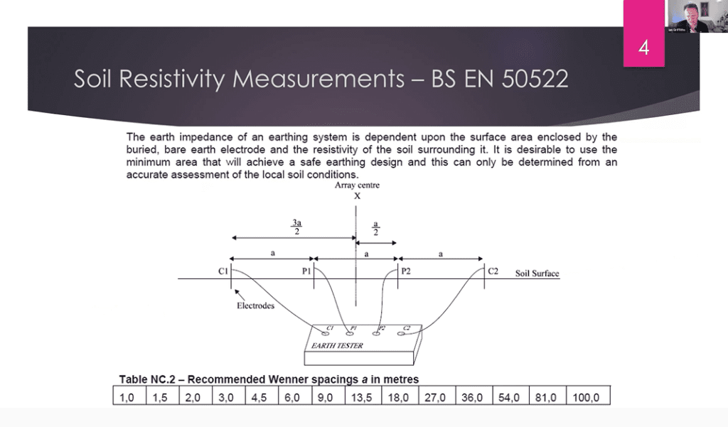
When Hugh is referring to the term a-spacing. For those that aren’t particularly aware, it is this spacing between each probe. So the probes are the electrodes that are stuck into the ground. You’ve got C1, P1, P2, C2 on this particular image. And it is that interprobe space which can be varied according. So that’s the term a-spacing.
The other thing was, I was just wondering whether to share the importance of soil resistivity.
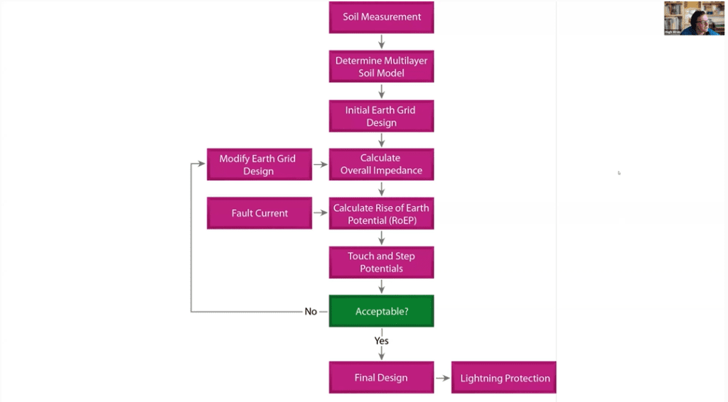
Hugh: So, as you can see, this is kind of the flow chart of the earthing design process. The first step is to do the soil measurement and determine your multilayer soil model. And that is the most important thing. That feeds all the way through to the final design. So this is why it’s essential to get it right.
Ian: So, thank you for watching. Thanks to Hugh and thanks to our supporting team in the background, making it all happen. And I look forward to seeing you next time—cheers for now.
Soil Resistivity Testing Methods:
Engage with us…
- Earthing Design Services & Lightning Protection Design – If high voltage power systems and lightning are causing you concern why not see how we can help with a quick ‘live chat’ below as a start.
- XGSLab – A complete software tool for the simulation of Power, Earthing, Grounding and Lightning Systems, get in touch to request a free demo.
- Get Certified – Start your journey to become certified in Power Systems Earthing & Design.