The correct sizing of high voltage earthing (grounding) conductors is crucial for the safe and efficient operation of any electrical system. The size of the grounding conductor should be determined based on the maximum fault current that the system is likely to experience. As well as the voltage level and the type of earthing system being used.
In general, the grounding conductor should be sized to carry the maximum fault current for a specified duration without overheating or causing damage to the conductor or surrounding equipment. This can be determined using industry-standard calculation methods and guidelines. Such as those provided by the National Electric Code (NEC) or the International Electrotechnical Commission (IEC).
What size conductors should I use?
There a simple table I can use for this HV high voltage earthing design project. These are great questions and often asked. This post answers these questions together with the choice of conductor materials and jointing method within a high voltage earthing design project.
Assessing conductor size is entirely dependent on the electrical configuration and the load that the conductor must take. For example, an above-ground bonding conductor serves to transfer current with minimal voltage drop, from A to B. A directly buried conductor has an additional purpose. That of leaking the fault current or voltage into the local geology (as part of an electrode).

When considering Lightning, the same conductor above might also see a high-frequency component and which will impose yet another requirement.
High Voltage Earthing Design Considerations
In IEEE-std80 Guide for Safety in AC Substation Grounding, section 11 – states the basic requirements are:
Each element of the grounding system, including grid conductors, connections, connecting leads, and all primary electrodes, should be so designed that for the expected design life of the installation. The element will :
- a) Have sufficient conductivity, so that it will not contribute substantially to local voltage differences.
- b) Resist fusing and mechanical deterioration under the most adverse combination of a fault magnitude and duration.
- c) Be mechanically reliable and rugged to a high degree.
- d) Be able to maintain its function even when exposed to corrosion or physical abuse.
High Voltage Earthing Materials
High voltage earthing (grounding) materials include the following:
- Copper: Copper is a commonly used material for grounding conductors because of its high conductivity and resistance to corrosion.
- Aluminum: Aluminum is also used for grounding conductors, but it is not as common as copper due to its lower conductivity.
- Steel: Steel is used for grounding electrodes, such as ground rods or plates, because of its strength and durability.
The choice of material will depend on the specific application, system requirements, and compliance with industry codes and standards.
Dealing with the Heat From HV Current Flow
So now we’ve covered the materials widely used for HV earthing. Point ‘b’ from IEEE-std 80 above calls for the conductor to retain its mechanical strength when exposed to a fault.
Dealing with the heat generated from high voltage (HV) current flow in earthing (grounding) systems involves several methods:
- Proper sizing of grounding conductors: The size of the grounding conductor should be determined based on the maximum fault current that the system is likely to experience. As well as the voltage level and the type of earthing system being used. By ensuring that the grounding conductor is properly sized, the heat generated during a fault can be minimized.
- Using heat-resistant materials: Using materials with a high resistance to heat, such as graphite, can help to dissipate the heat generated during a fault.
- Using heat sinks: A heat sink is a passive heat exchanger that transfers heat generated by an electronic device, to a fluid medium, such as air or a liquid, where it is dissipated. This method can be used to dissipate the heat generated by a grounding conductor.
- Using cooling systems: A cooling system can be used to dissipate the heat generated by a grounding conductor. This can be achieved through forced air cooling, water cooling, or other methods.
- Providing enough spacing between conductors: Providing enough spacing between conductors in an earthing system can help to reduce the heat generated by the current flow.
- Regular maintenance: Regular maintenance of the earthing system. Including visual inspections, can help to identify and address any issues that may be contributing to an increase in heat generation.
Up to this point, we’ve discussed conductor conductivities, materials and thermal-mechanical characteristics.
Another consideration for high voltage earthing is the method of the joint between the conductors.
High Voltage Conductor Joints
High voltage (HV) conductor joints are the connections between two or more sections of a conductor that allow for the continuity of the electrical circuit. The design and installation of HV conductor joints must meet certain criteria to ensure safe and reliable operation.
- Mechanical Strength: The joint must be able to withstand the mechanical loads imposed on it without failure, such as tension, compression, and bending.
- Electrical Continuity: The joint must provide electrical continuity between the conductors, with minimal resistance and inductance.
- Insulation: The joint must provide insulation between the conductors to prevent short circuits and ground faults.
- Environmental Protection: The joint must be protected from environmental factors such as moisture, temperature, and corrosion.
- Reliability: The joint must be reliable and have a long service life.
Types of HV conductor joints
There are different types of HV conductor joints that can be used, including mechanical joints, compression joints, and soldered joints.
- Mechanical joints: These use mechanical connectors, such as clamps or bolts, to hold the conductors together.
- Compression joints: These use a compression sleeve and a die to compress the conductors together, creating a secure mechanical and electrical connection.
- Soldered joints: These use a solder material to make a connection between the conductors.
Joints in the conductors are; as critical to current-flow as the conductors themselves. The jointing method must not allow the joint to introduce excessive resistance. Therefore, the selection of the jointing method will impact the HV earthing system’s thermal resilience massively. This thermal resilience is why welding joints are the go-to choice for the high voltage earthing system.
Welded joints achieve the nearest physical match to the native conductor itself and are the gold-standard in conductor jointing. They accomplish a molecular similarity to the native material’s conductivity, as well as similar mechanical robustness.
Here’s an example of a safe method of igniting an exothermic weld.
A Word of Caution
Bolted joints and clamps made up of multiple parts which can creep and loosen over time. Loosening adds resistance across the conductor’s joints. Which as previously mentioned… is not a good thing (thermal runaway is a topic for another day).
Bolted joints fall into the category of mechanical joint methods and have a derating factor to keep the conductors operating at lower temperatures. When designing a high voltage earthing system, this means the seemingly unrelated selection of jointing method will also impact the conductor size calculation.
IEEE adiabatic equation
The IEEE adiabatic equation is a formula used to calculate the maximum safe current that can be carried by a conductor without causing an excessive temperature rise. The equation is:
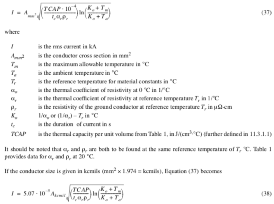
The IEEE adiabatic equation is used in conjunction with the ampacity tables provided by the National Electric Code (NEC). Other industry standards to determine the appropriate size of a conductor for a given application.
It is important to note that the adiabatic equation is based on the assumption that the heat generated by the current flow is dissipated rapidly through the surrounding air. And that the temperature of the conductor rises instantaneously. In reality, the heat dissipation may not be so fast and the temperature of the conductor may take some time to reach the maximum limit. Therefore, it is important to also consider other factors such as the thermal resistance of the insulation and the environment in which the conductor is installed.
In Summary
So there you have it. Without going into great detail, the following factors influence conductor sizing in high voltage earthing design:
- The magnitude and duration of fault current (i.e. the heat source),
- The method used for the joint
- The conductor material
- The conductor’s role in the high voltage earthing design
These factors may vary project by project. So, using a particular size of the conductor on a previous project does not mean that the same will apply to the next project. Which involves calculating conductor sizes (adiabatic equation) to fit the particular requirements of the high voltage earthing design project is usually very necessary.
Engage with us…
- Earthing Design Services & Lightning Protection Design – If high voltage power systems and lightning are causing you concern why not see how we can help with a quick ‘live chat’ below as a start.
- XGSLab – A complete software tool for the simulation of Power, Earthing, Grounding and Lightning Systems, get in touch to request a free demo.
- Get Certified – Start your journey to become certified in Power Systems Earthing & Design.