Recently, I received a call from a client in the Nordic region to review an earthing system problem – the client explained they had “… unexplainable noise on their clean earth” and could we help solve it?
50 Shades of Grey … but one that Matters in earthing design!
I should explain … the term ‘clean earth’ was commonly applied in the mid-to-late 1990’s to describe a separated earth electrode which consisted of a grid, earth ring, or other arrangement/combination that maintained isolation/separation from a power source.
The received wisdom of the day was that maintaining separation of functional, safety, signal or chassis earth systems avoided cross contamination of ‘noise’ (EMI – electromagnetic interference) between the earth systems – and therefore, could be considered a healthy approach … especially for noise-sensitive environments such as data-centres, radar, wafer-fabs and other high tech electronic biased facilities of the time.
So, coming back to the call – after some to-ing and fro-ing it was agreed to survey the site and get eyes on the problem.
Survey Tasking
- Visual inspection of above ground arrangements
- Earth measurements (resistance)
- Continuity tests from point to point
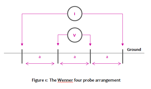
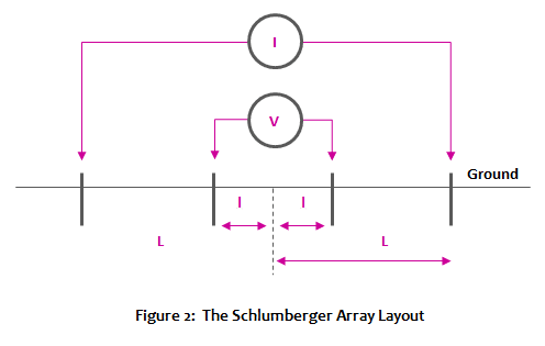
- Soil Resistivity soundings (Wenner)
- Sample Joint measurements
- Radio-detection of buried arrangements
Test Equipment
The measurement equipment used for the task included:
- Cable Avoidance Tool (CAT) and signal generator – III generation
- Digital low resistance ohm-meter with a 10 A signal current
- Earth Tester with 150 V signal injection
- Soil Resistivity tester with up to 800 V signal injection, 1D and 2D capable
- 2,000 m of test leads and probes
GreyMatters Findings
The earth systems were installed into three distinct systems – 1) a clean earth for the data network – functional earth, 2) another for the power systems – safety earth; and 3) a third grid for the generators.
Separation between earth systems was minimal – indeed, a number of ducted routes were populated by all three earth systems, together with HV/MV power and signal cabling for 10’s of meters at a time.
Furthermore, the local geology and soil structure found in the Nordic region was solid Granite bedrock from as little as 200 mm deep, with only a dry, thin layer of topsoil covering the rock underneath.
This kind of geology presents a unique challenge:
- Sounding for Soil Resistivity in weathered granite bedrock found in this region requires an usually high signal-to-noise ratio In order to penetrate the solid geology to sufficient depth.Without a high enough signal strength, large errors can be returned – given the fundamental role and importance an accurate soil model plays in all subsequent earth designs; errors at this stage can magnify errors in the final earth design – so the importance of robust capable instrumentation and competence cannot be understated.
- Certain rocks like Granite radiate EMF and can be a source of electrical interference, which needs to be accounted for through signal manipulation on the instrument to avoid another source of error.
Outcome
After the site survey, the data was collated and processed into a virtual model of the site using the electromagnetic field modules of the engineering simulation software, CDEGS.
A finite element virtual model was developed to represent the entire ‘system’ (electrically) in a wire frame format from the multi-layer soil structure, the electrical power system, signal cabling and above-ground duct routing, etc.
With the HV and MV electrical power system energised and with a load applied, a steady state scenario was developed which allowed the precise identification of the location where the electrical noise was being picked-up – through induction from the unshielded power cables.
Two further scenarios were developed to explore the effect of maintaining the existing site strategy of separation between earths, and the other scenario, to explore the appropriate combining of signal and main earths. The detail of which will be explored in a future post – one for another day!
Conclusion
Standard practices up to the early 2000’s consisted of very little, if any, pre-site measurement – the importance of soil resistivity and the pivotal role it plays in providing robust SAFE earthing design has only recently (during past 10 years) transferred from being perceived as the reserve of academia to enjoy a more wider recognition and acceptance in the practical world as part of a scientific approach to safe Electrical Power System design.
Pretty much all of the previously held wisdoms, precedents, assumptions and practices to do with Earthing/Grounding design have been challenged over the past decade.
Through the application of good science, connected thinking and plain old fashioned “dogged persistence” from a few well-respected champions on the various international standards committees. The resulting incarnations of IEC/EN 50522, 50122-1 (for rail applications) have created a robust process/approach for Earthing above 1 kV, based on good science, which when applied will protect critical assets and life, more effectively.
Gone are the days of blindly banging in electrode after electrode in pursuit of reaching a mystical “1 ohm” for your earth/ground resistance without any consideration for its purpose or what the human body can withstand (electric shock).
Anything but Grey
Today we stand on the shoulders of people like Dalziel, who have quite literally put their own lives on the line during experiments, so that we or the people benefiting from our earthing/grounding designs, don’t have to – thank goodness!